Necessary supplies/tools:
18ga ground wire
RG-58A/U shielded wire
Soldering iron
Solder
Heat shrink tubing
Plastic wire looming
electrical tape
wire stripper
Dikes (wire cutters)
In the never ending quest to get rid of phantom knock, many people look towards rewiring the knock sensor to the ECU. A 16+ year old knock sensor wire can be brittle or cracked, and it might have too much resistance, which can lead to bad knock readings. You can check for continuity and resistance from the knock sensor wire harness to the ECU with a volt meter by unplugging the ECU plug and tapping into pin #9, and unplugging the knock sensor in the engine bay and tapping into the positive wire in the car side harness (I forget which color is positive, but this check will tell you if you try each wire). I don't know what the spec is for how much resistance you should see, but if it's more than a couple ohms, or it jumps around between high and low resistance with a "wiggle test", it might be time to replace the wire. Unfortunately, there's very little info on how to do this properly. A quick look on forums will reveal answers ranging from "get a shielded wire" to "run a regular wire and call it a day", and don't even think about getting a straight answer on how/where to find the proper type of shielded wire or how to hook it up. It took me a bit of time, but once I figured it out I realized it's actually pretty simple. Sorry for the lack of photos...I only have a couple of pics plus a few diagrams to show of the finished product.
First, here's a diagram from the factory service manual:
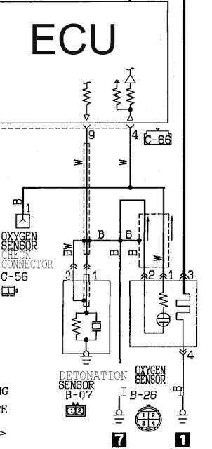
The dotted lines in the diagram represent the wire shielding. The diagram is a little deceiving b/c the grounding of the shielding to the knock sensor ground wire and chassis happens inside the car right next to the ECU rather than in the engine bay. Notice that it also connects to the shielding and ground for the O2 sensor (I didn't worry about that on my car since I've eliminated the factory O2 sensor). It's a little hard to understand, so check the diagram at the bottom of the post that I made if it doesn't make sense.
The biggest setback I had in doing this was finding the right kind of shielded wire. People on the forums said "just hit radio shack and ask for shielded wire". *PFFT* Radioshack is a toy store now. For shits and giggles I walked into one and asked and I got really weird looks, followed by "well, this is shielded..." (they pointed at your run of the mill hookup wire that's *insulated*). Then I went to a pretty good electronics store, but all they had was bundled wire with foil shielding. I was looking for mesh shielding b/c that's what's in the car from the factory, and the closest I could find was coax cable like for cable TV, but it was a cable rather than stranded wire. Finally I hit FRY's (an electronics chain here in CA) and just started perusing their coax cable section. I stumbled upon shielded cable with stranded wire in the middle, just like the wire from the car! It was labeled RG-58A/U, and it's pretty easy to order online once you know what you're looking for.
First thing you need to do is snip the positive and negative wires on the car side pigtail on the harness and tape off the factory wires. Then use your wire stripper to expose the stranded wire on the shielded wire. Solder this wire to the positive side of the pigtail. Then solder the regular ground wire to the negative side of the pigtail. Run these wires through the firewall next to each other (I used the big rubber grommet behind the battery on the passenger side). I used the hanger wire method of attaching the wires to one end of the hanger wire, then forcing the hanger through the firewall and pulling it through from the other side, fishing the electrical wire inside the car.
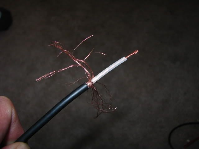
This is where the wiring gets a little complicated. Looking at the factory wiring will help you get a picture of how to do this. What you want to do with the shielded wire is strip the outer most insulation to expose the mesh shielding.
Pull the mesh shielding away from the wire a few inches like this:
Then you'll want to twist it together like this:
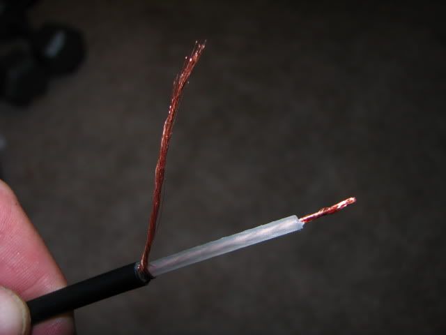
Once you've done that, strip the new Knock Sensor ground wire to expose it and twist it together with the shield mesh from the shielded positive wire. You can then use a butt connector to attach the twisted pair to a short single piece of ground wire and ground that to the chassis. Remember to shield all of this with heat shrink or electrical tape.
Next, cut the wire going into pin #9 on the ECU, but leave some wire so you have room to solder the new knock sensor wire. Don't forget to put the heat shrink tubing on first before you twist the wires together for soldering. All that's left after that is putting wire looming over the new wires, and tucking them away. Be sure to do a continuity test again between the positive side of the pigtail and pin #9 in the ECU harness, as well as the negative side of the pig tail to ground. Reconnect the pig tail to the knock sensor and you're set!
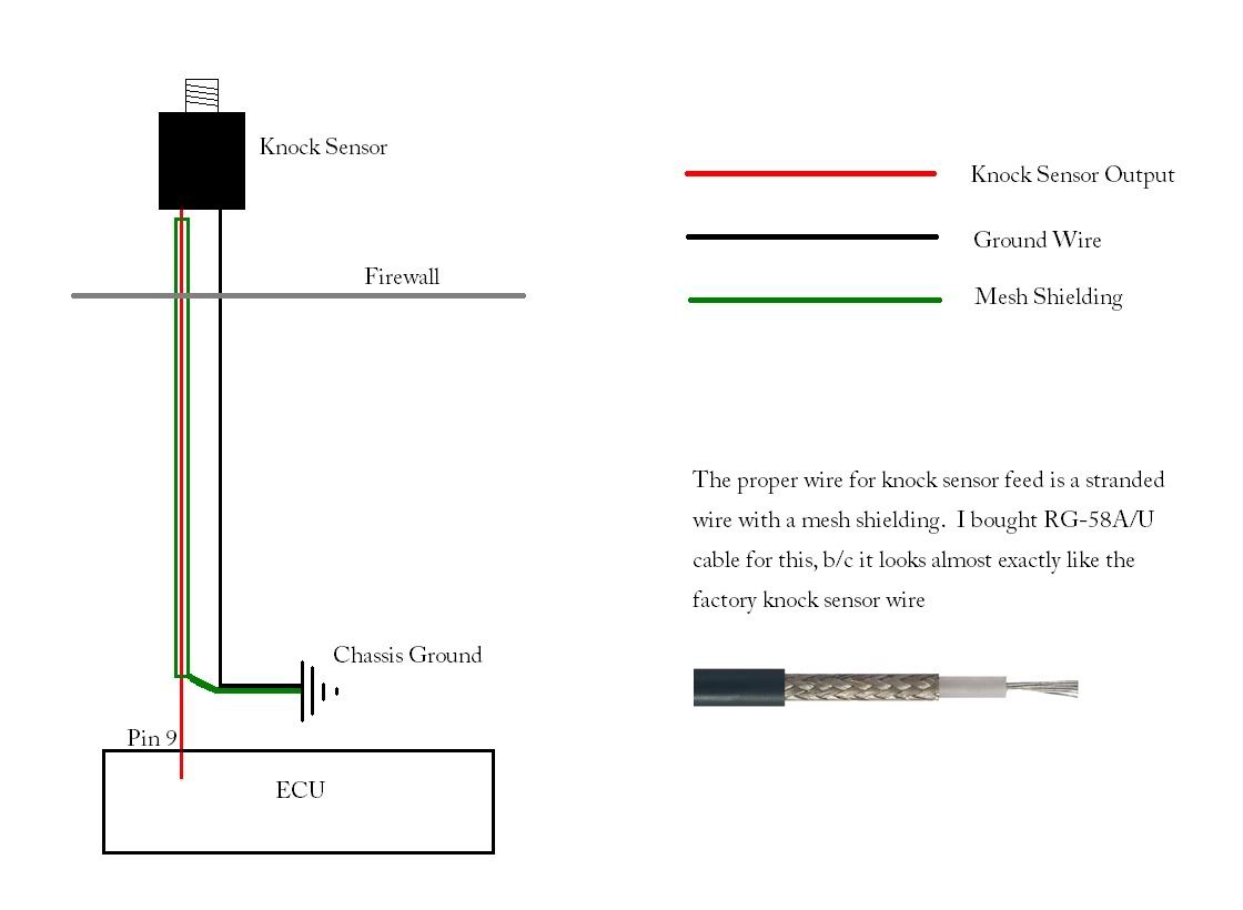
Here's a diagram I made of the finished product (click on it for high res):