Well, it's been a while since I've done a tech writeup that involves installing some go-fast parts, and what better way to get back into it than one of the best mods you can put on a car...A GIANT TURBOCHARGER! =D
So, here's the story on this turbo. The sport compact scene (or "import scene" if you prefer) realized a few years ago that you can pull a variety of Holset turbos from semis and Ram Charger Cummins Diesels and throw them on a 4 cylinder engine for some major power gains. That alone doesn't seem all that special, but the thing that makes the holsets so desireable is how fast they spool up on a small displacement motor. I hear that quick spooling is native to a diesel turbo b/c diesel engines have colder, slower moving exhaust which necesitates quick spool times. What that means is you can buy a used Holset for a few hundred bucks that will flow as much and spool as fast as a ball bearing turbo that would set ou back $2,000-$3,000! If that's not enough, the Holset turbos are seriously built tough since they are intended for extended operation on heavy duty vehicles. From what I hear you can thrash a Holset pretty good and it will keep going.
In the DSM world, the most popular Holset turbos to bolt onto a 4G63 engine are the HX35 and HX40 turbos. I chose the HX35 because it will spool faster and be MORE than enough for the kind of power I want out of a street car. DSM owners have been putting down well over 400hp and making low 11 second passes on the HX35. Most people are seeing full spool by 4,000rpm on 2.0L engines. With my 2.3L stroker motor I was seeing 23psi at 3,000rpm on my EvoIII 16g GT turbo. I hope to be spooling by 3,500 with the HX35, which will be great for such a large turbo.
The first step in the process of upgrading to an HX35 was finding one (obviously). You can buy brand new setups for around $1,000 or you can buy them used on eBay or at the junkyard and get all the parts you need to get it to bolt up to a DSM. NOTE: if you buy a used Holset, be sure to look out for counterfeit turbos!!! Click here for information on spotting counterfeits. They are sold all over eBay and Craigslist, as well as in the classifieds sections of automotive forums. Here's a very corperate looking demonstration video on why NOT to get a counterfeit:
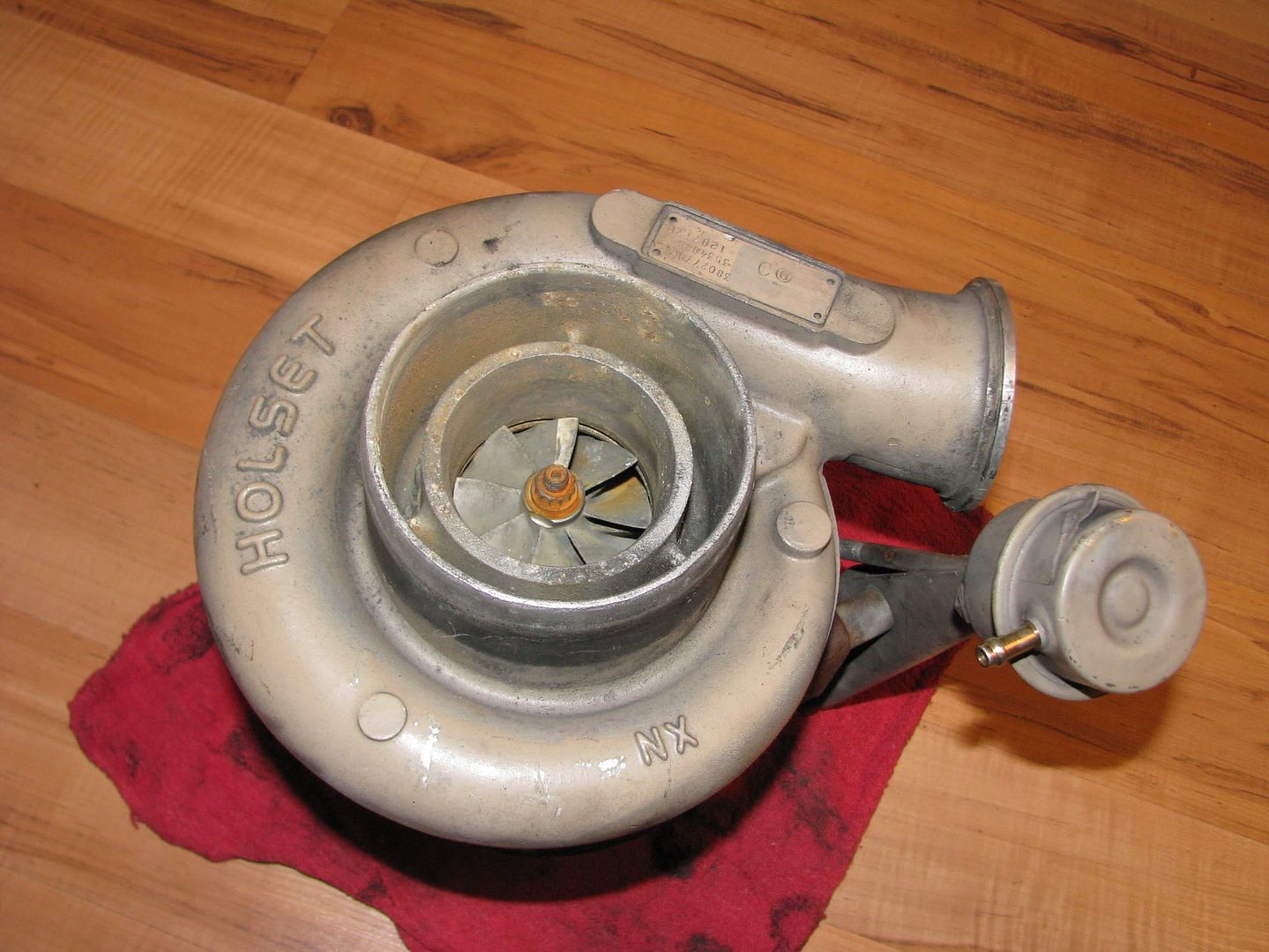
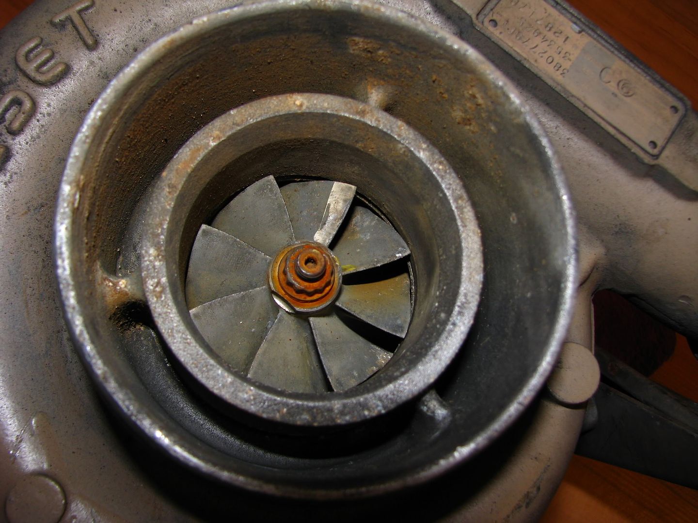
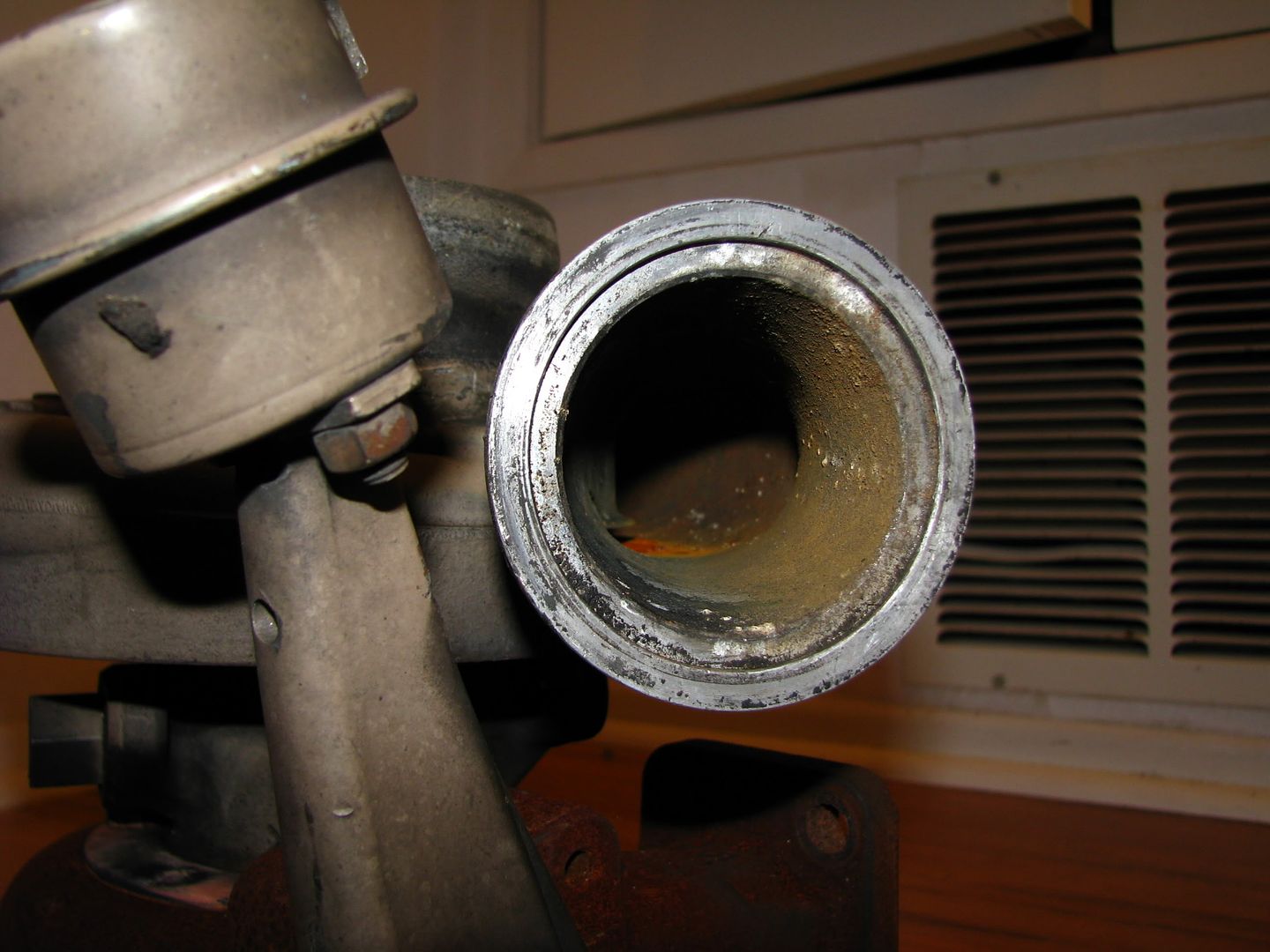
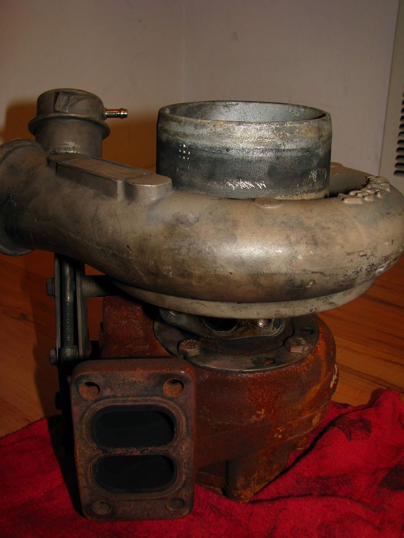
Well, thanks to some advice from a friend of mine I knew of a spot in a local junkyard that was ripe with holset turbos and I found a perfectly good HX35 for $120. What's even better is that it was a half-off weekend, so I got it for $60!!!! =D Deal of the century! Here's some pictures of how the turbo looked when I pulled it at the junkyard:
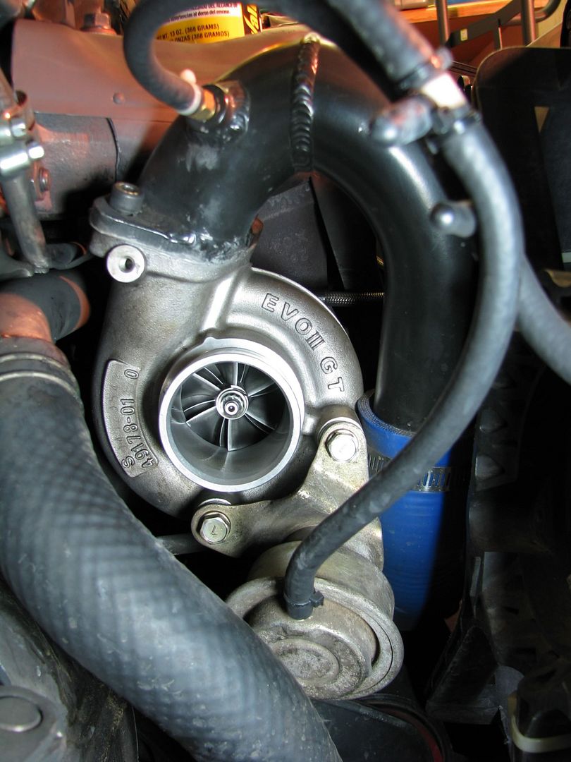
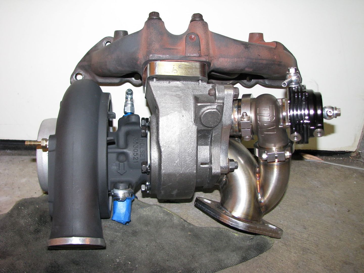
To give you an idea of how much of an improvement this is here's a pic of the EvoIII 16g GT I was running:
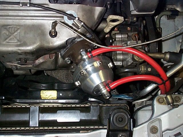
Okay, so it *looks* dirty as hell, but it was a real find. The compressor and turbine blades were in great shape, and there was no shaft play! I showed it to Sam at RRE to see if it was in need of a rebuild. He said rock it as-is. Well, now I have an HX35, but I have to decide how to get it to bolt up to the DSM. You have a couple of options at this point. The Holset turbine housing will bolt up to a T3 style manifold which you can buy aftermarket for a DSM, but I wanted to go with a more sleeper route and bolt it up to my Evo III exhaust manifold. Bullseye Power (BEP) makes aftermarket turbine housings for Holsets that bolt right up to the DSM manifolds. You can buy them at Tim's Turbos. It's a .55a/r, which is a bit restrictive for the HX40, but is enough to see the full potential of the HX35. I'll post some pics of the BEP housing further below. The other thing you need to think about when installing any turbo is what waste gate configuration you're going with. You used to be able to buy the BEP housings with an internal waste gate, but you can't anymore...but who cares since internal waste gates suck, right? You really need to go with an external waste gate to have proper boost control. My exhaust manifold doesn't have a provision for an external waste gate, but I didn't want to mount it there anyway because it's way too conspicuous:

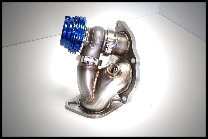
Instead, I decided to go with an O2 housing mounted waste gate. I bought a used Tial MV-S 38mm v-band waste gate off ebay and went to MAPerformance for the O2 housing. This should provide good boost control but draw a lot less attention. Also, since the waste gate routing is recirculated back into the exhaust, you don't end up with that loud attention getting O2 dump noise at full boost.
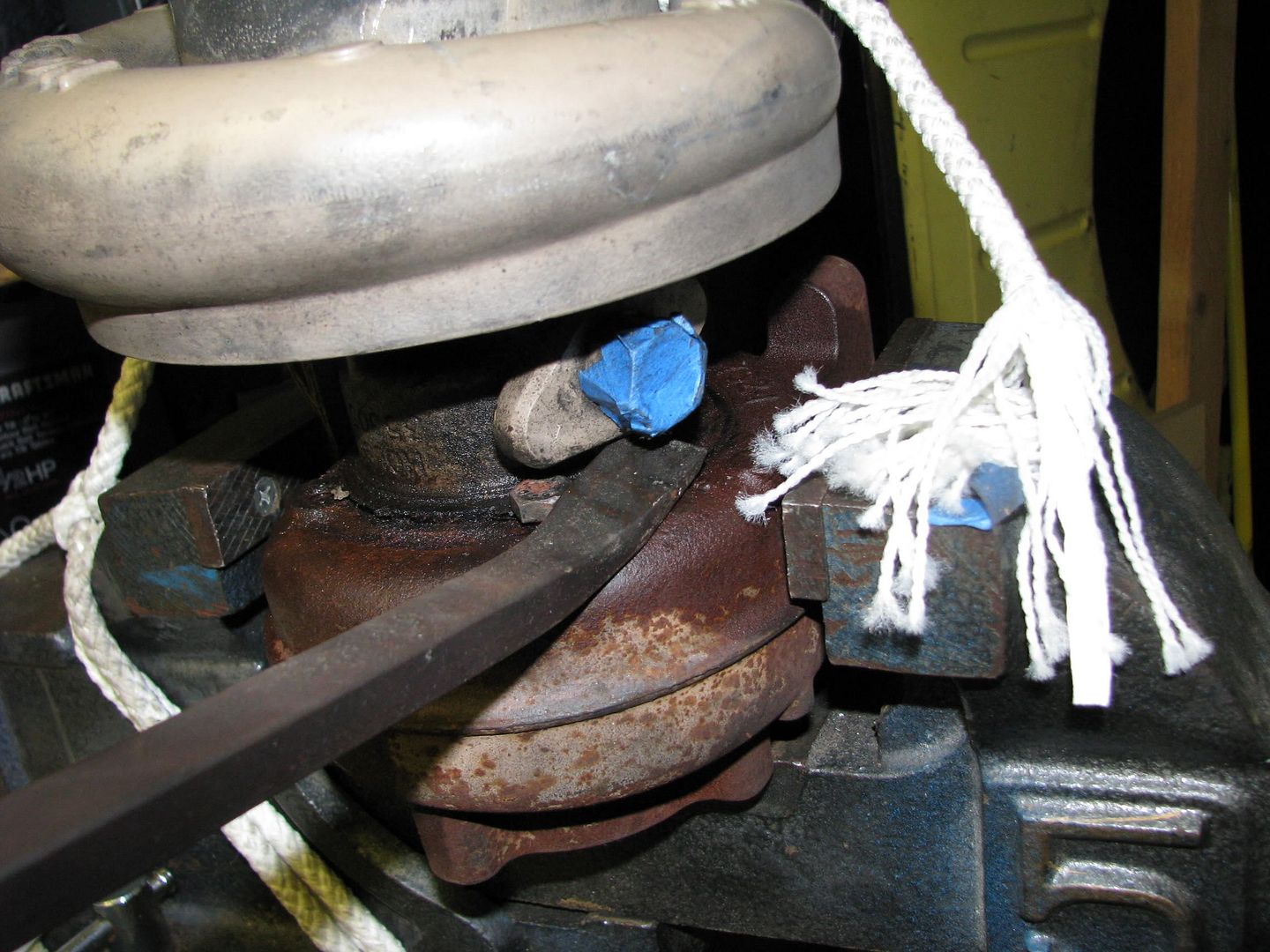
Alright, so at this point I had my HX35 and a plan for how to make it work. Time to get my hands dirty. First thing was removing the CHRA from the turbine housing. I removed the bolt holding the clamps into place:
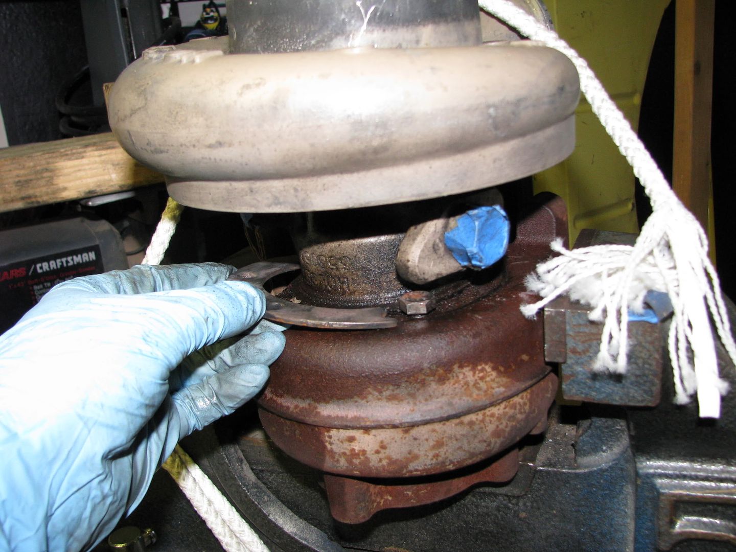

I thought it would be pretty easy to pull out, but after pulling at it and cussing a few times I finally got out the PB Blaster and a prybar:
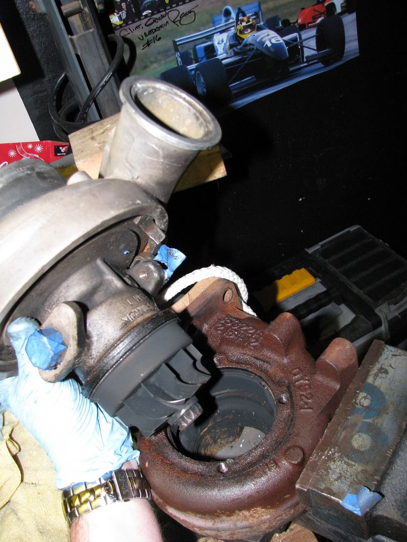
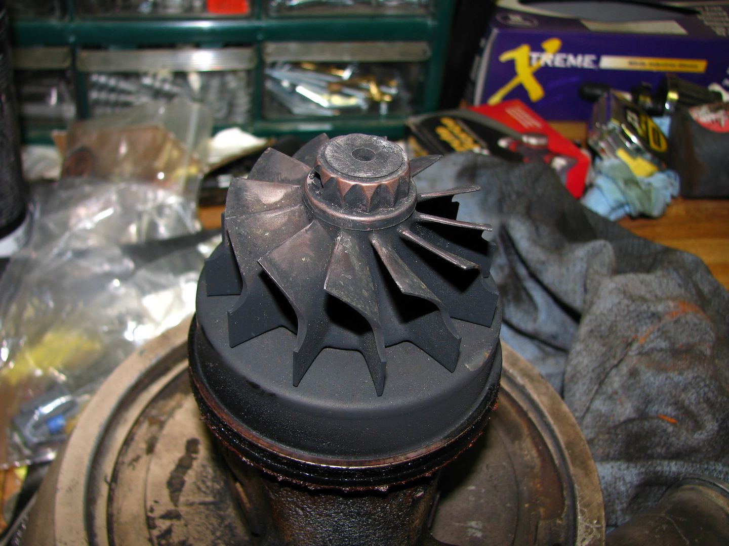
Sweet. Turbine blades look good. Next, it's time to move on to the compressor housing. I want to pull this off and get it media blasted to get rid of all the rust and grime as well as get a good look at the compressor blades. The Holset compressor housings are held in by a GIANT C clip. BE CAREFUL pulling this thing off. It's under a lot of tension. I don't have C clip pliars big enough, so I used channel locks which were prone to slipping off the tabs on the clip. To be safe I wore safety glasses and tied a rag around the housing to keep the clip from flying off.
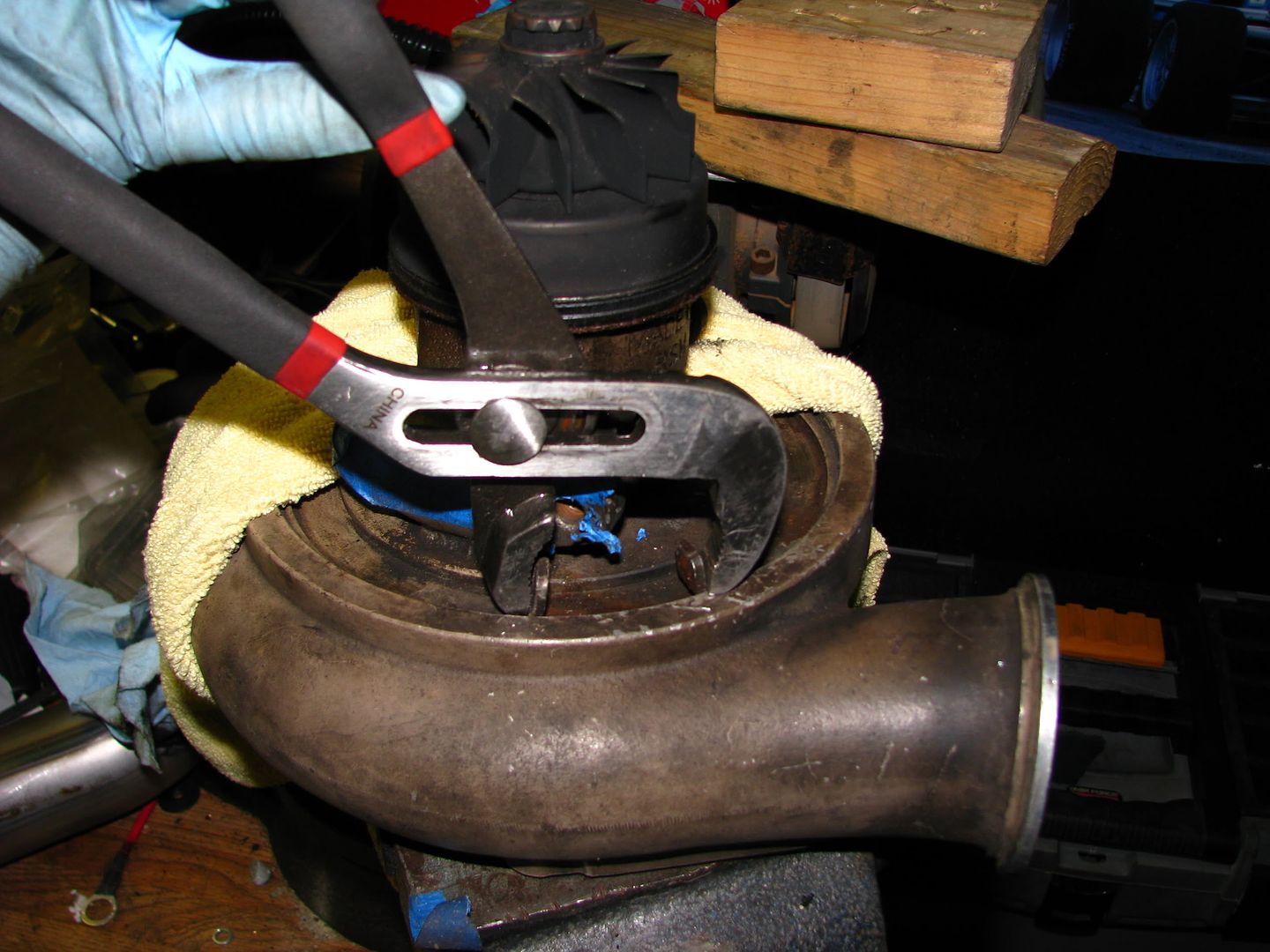
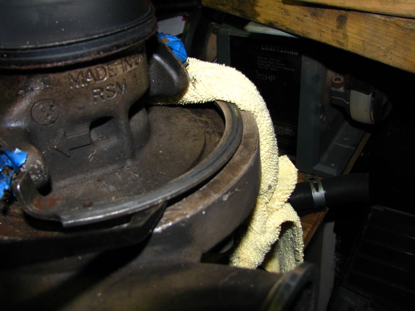
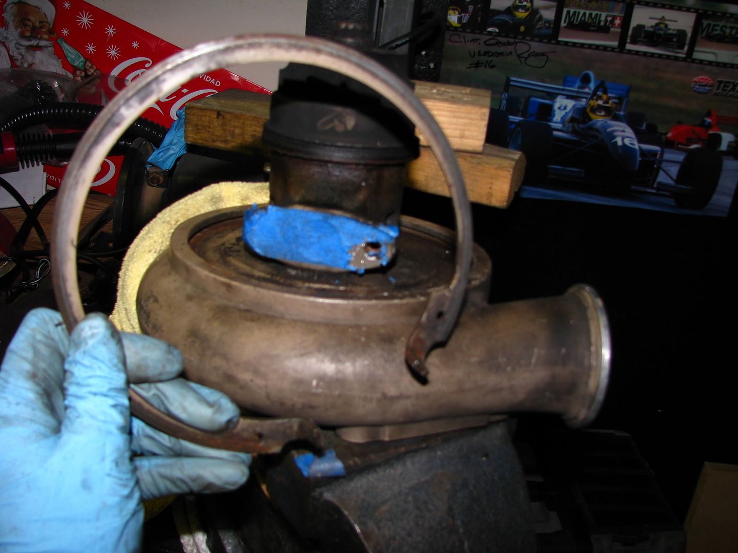
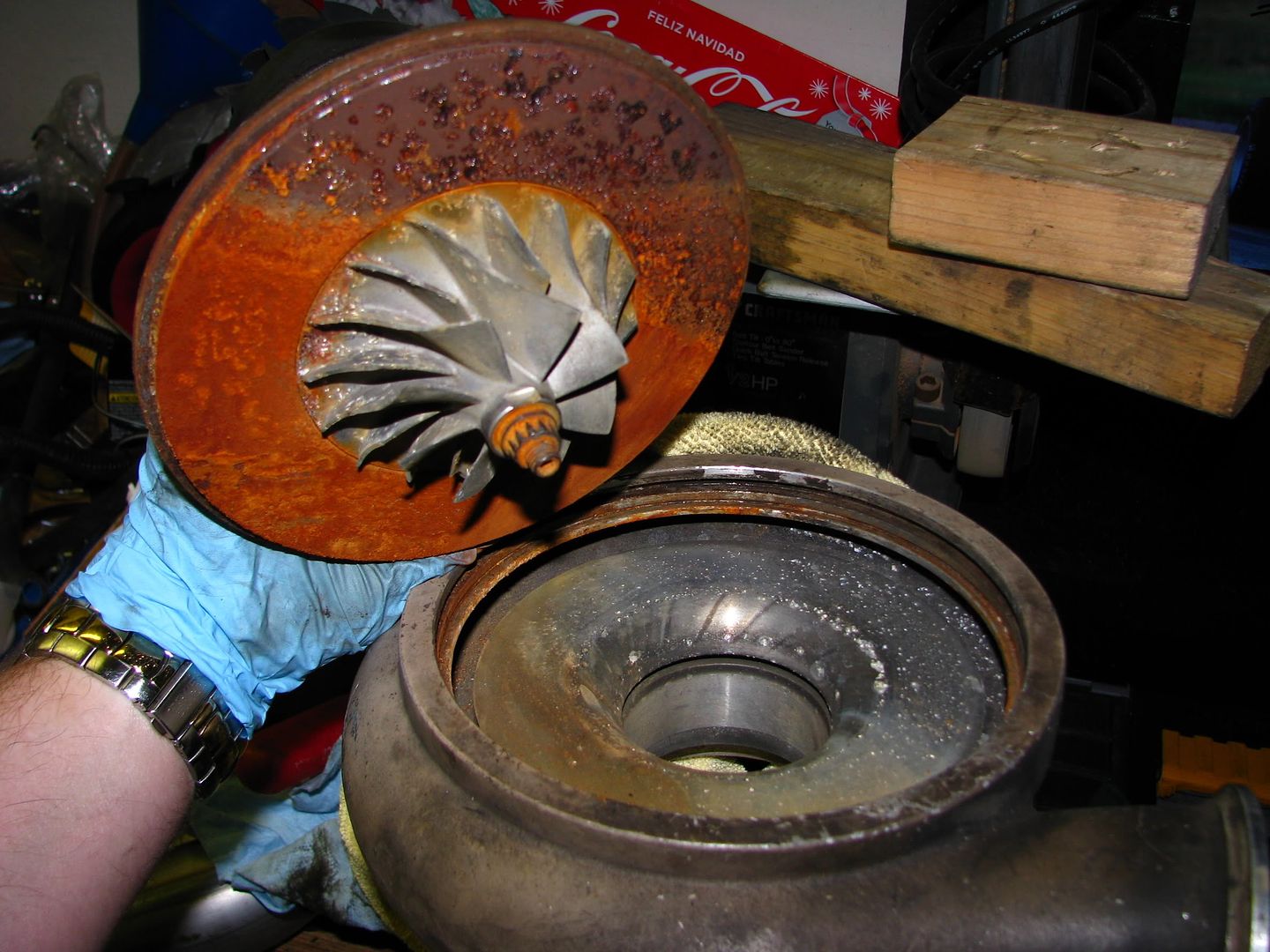
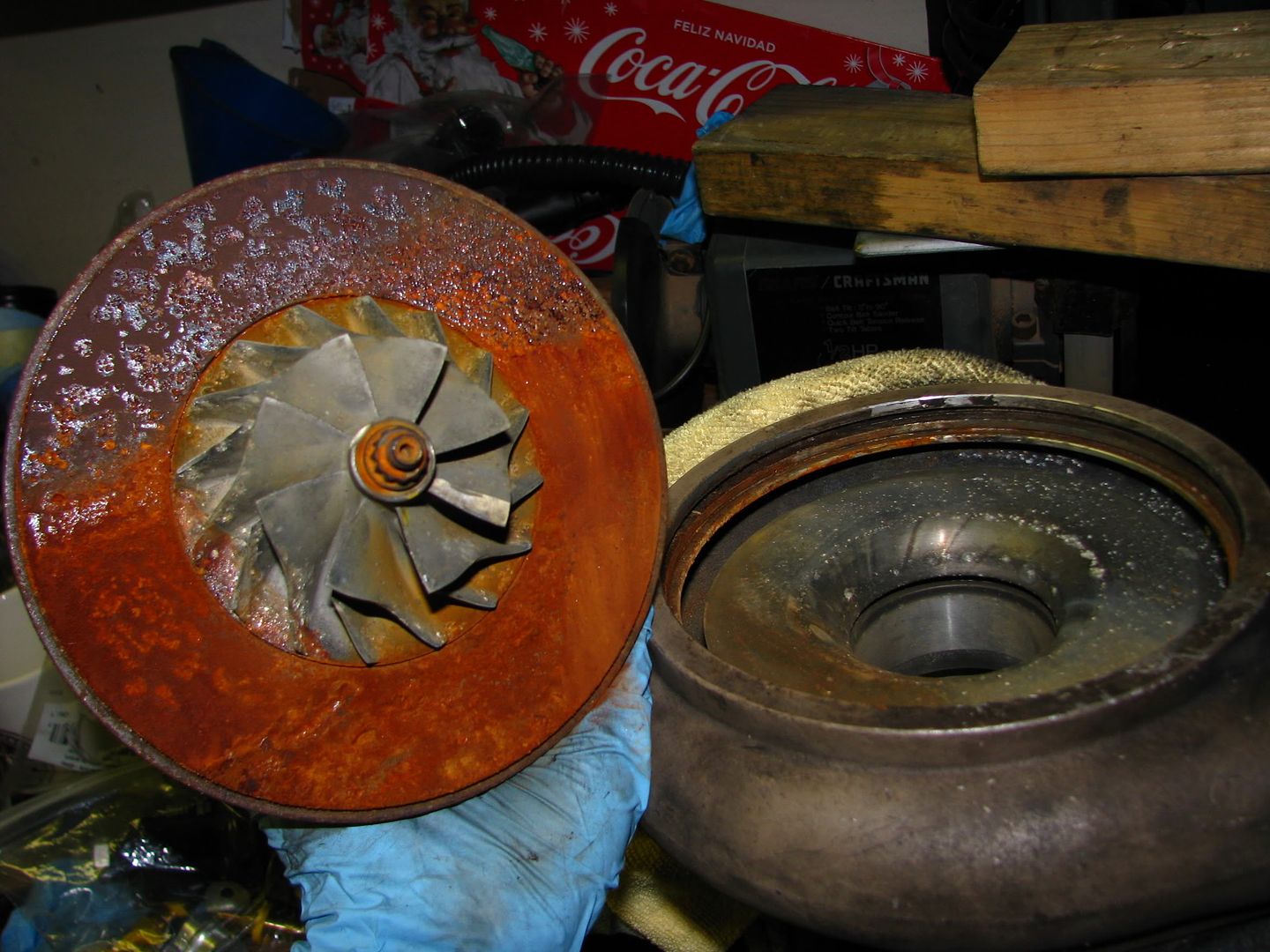
Wow! Look at all that rust in there! Something will have to be done about that, but first, look what showed up in the mail!! My BEP compressor housing! =D
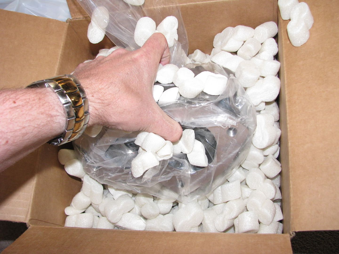

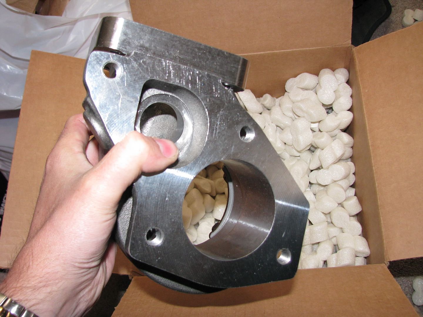
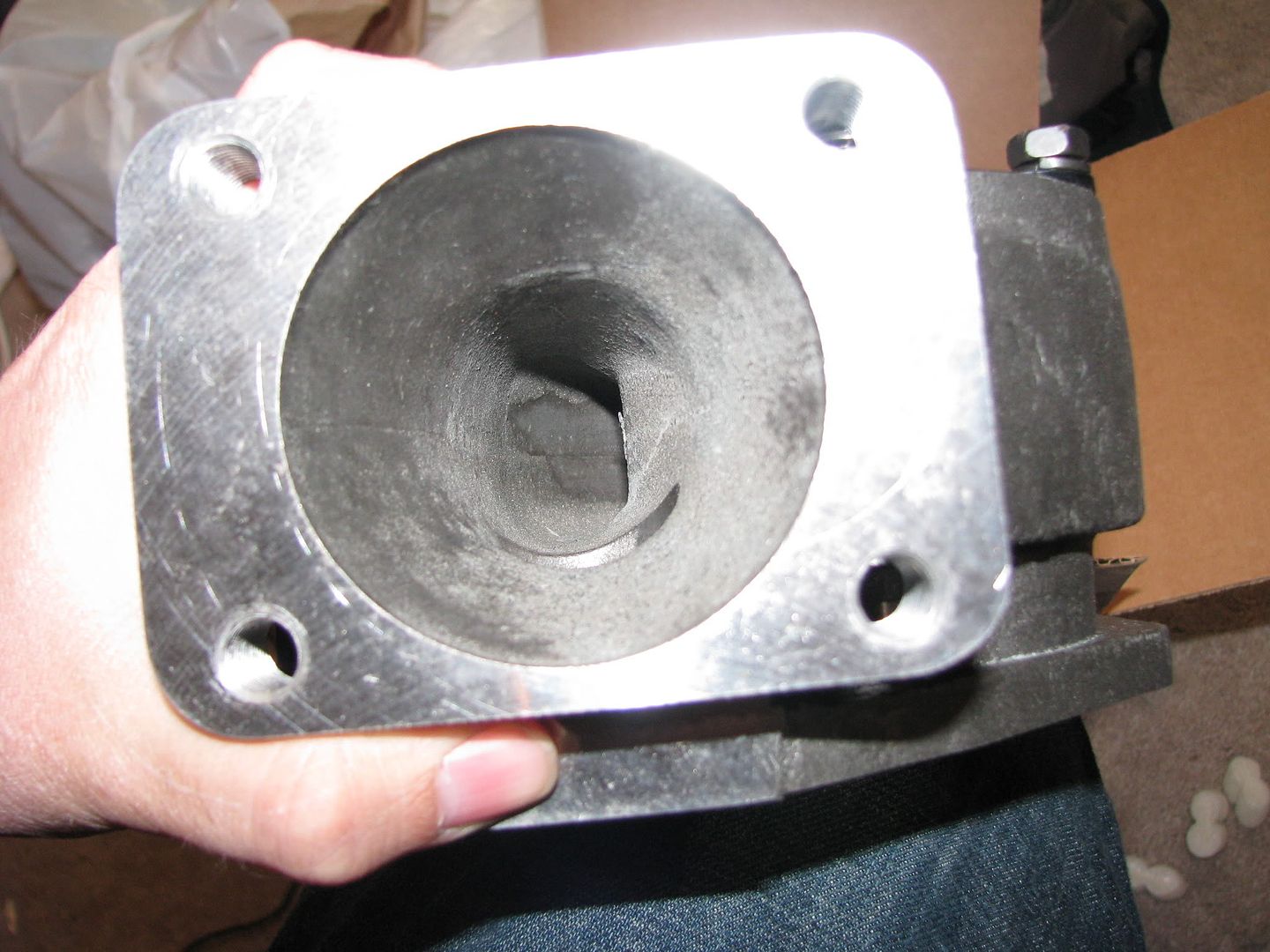
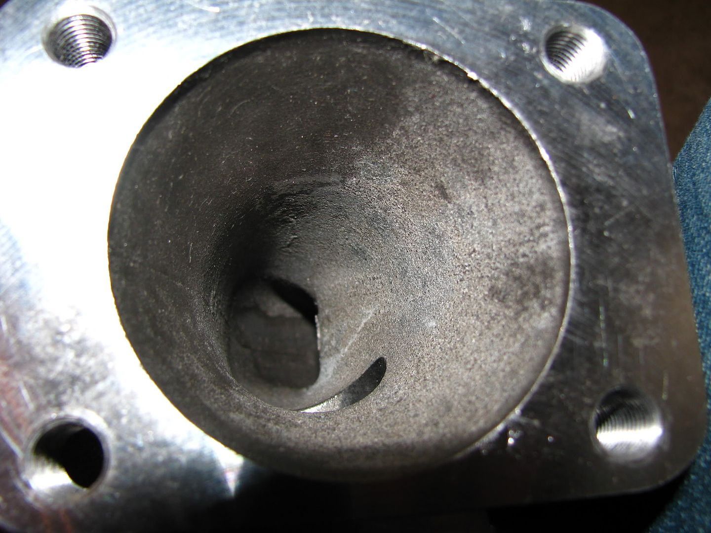
It looks spectacular, but I do have to mention it's heavy as hell. It's heavier than the housing that came with the holset, but it will bolt up to a stock DSM and it looks seriously tough. So, anyway, with the compressor housing pulled, I went ahead and cleaned up the compressor blades. I used a wire wheel on the CHRA face surrounding the blades, and then I cleaned the blades themselves with scotchbrite pad. I was afraid that anything more aggresive might eat into the metal and mess up the balance of the compressor/turbine wheels. It doesn't look perfect, but MUCH better than before! Here's a before/after comparrison:
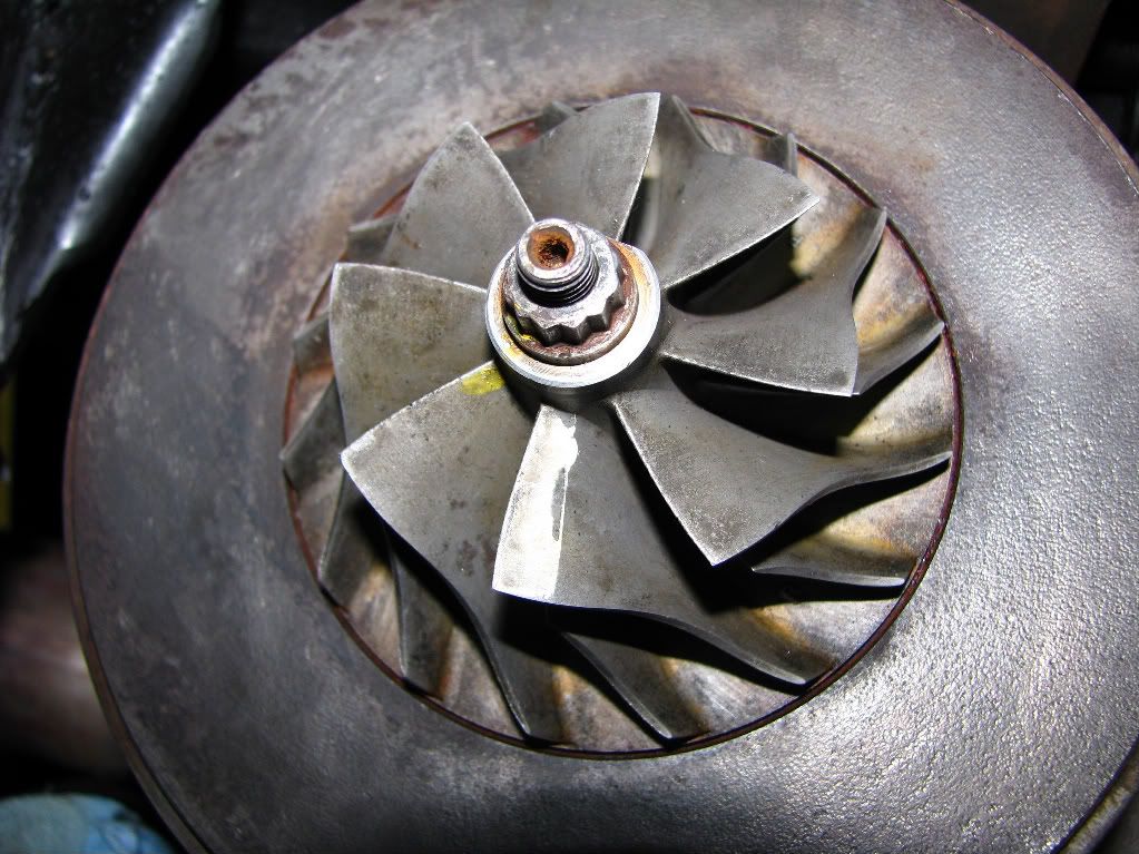
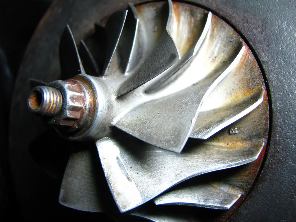
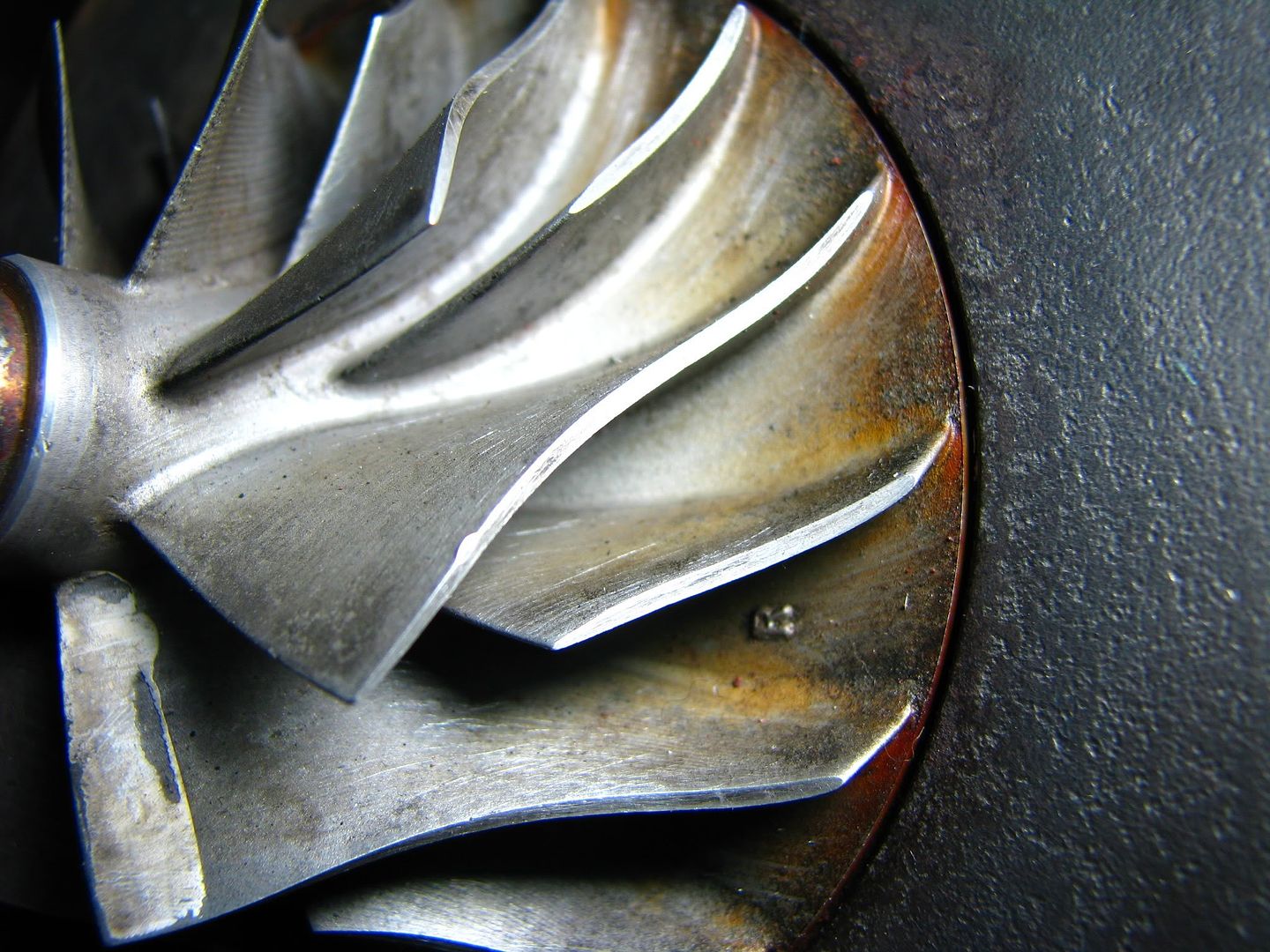
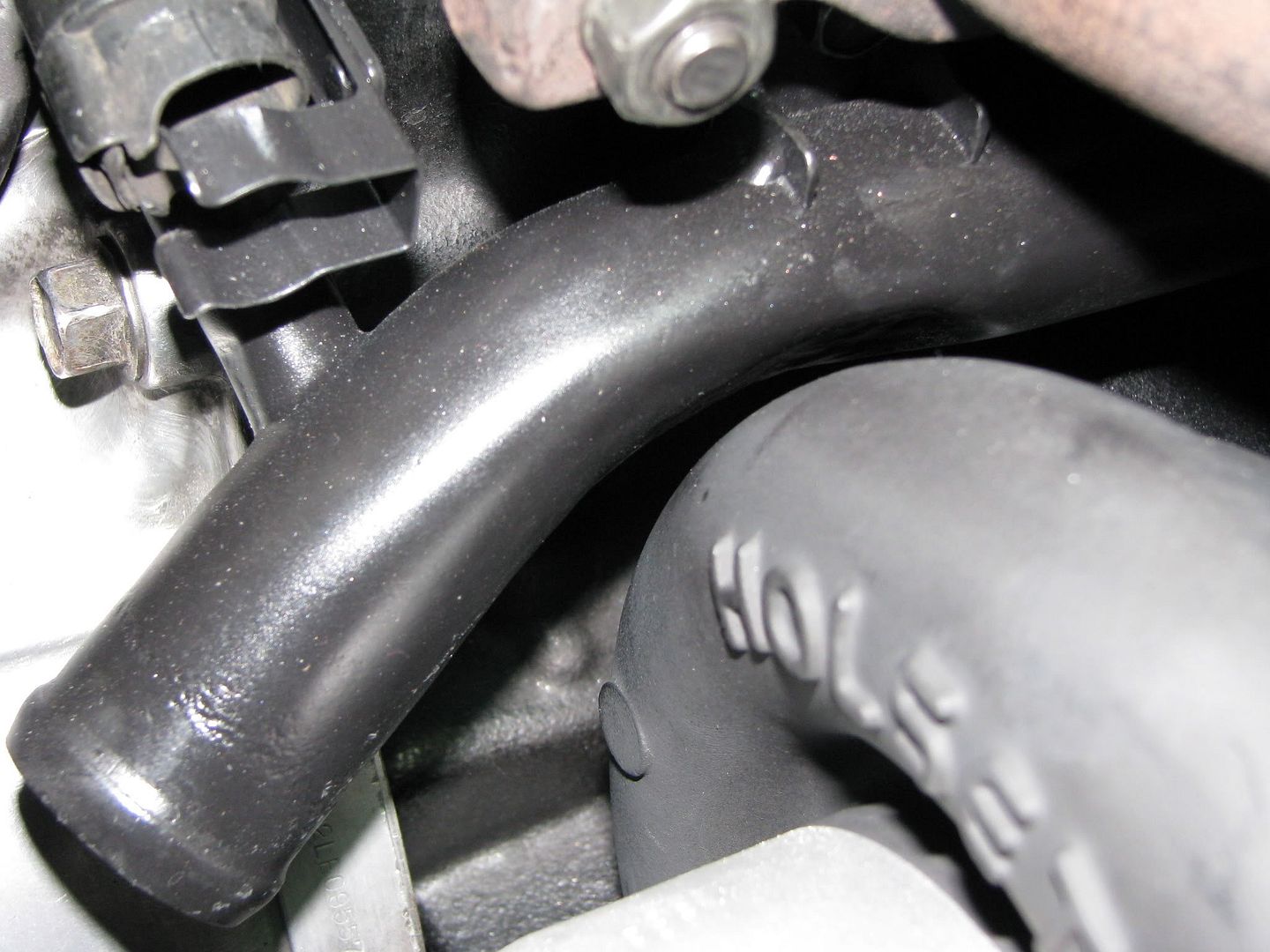
Alright. At this point I took a brake from the turbo while the compressor housing was off getting media blasted by my friend Dustin from LADSM, and I tended to some things in the engine bay. Obviously, I had to remove the old turbo, the exhaust manifold, O2 housing, and intake. There was only one modification that I needed to make to the car itself to get the turbo to fit (assuming you already have a FMIC like I did). Whenever you put a big turbo on the stock (or in my case the EvoIII) exhaust manifold, there is a chance that the big compressor housing will interfere with the water pipe directly behind it. Most people dent the water pipe a little bit to get it to fit, which is what I did. The ideal thing to do is get a non-turbo water pipe from an N/A 4G63 1g DSM because the Holset is oil cooled only and if you have the turbo pipe you have to find a plug for the water line, and the nipple for the water line in the pipe is very close to where you need to dent it to get the turbo to fit. The non-turbo pipe eliminates the extra water line and makes it easier to dent. Once I got the compressor housing back (thaks Dustin!) I test fit the turbo to see where the clearance issue was with the pipe. I marked it, pulled it off, and beat the hell out of it with a BFH. I wrapped rags around the hammer in an effort to keep from marring the pipe up too much while denting it. When I was finished, I painted the water pipe. For good measure, I pulled off the thermostat housing since it looked like crap, pulled the sensors, cleaned it off, and painted it too. While I was at it I painted the shifter cable bracket since it was looking old and crappy. I used Rustoleum high temp BBQ paint flat black, and finished it with VHT flame proof high temp clear coat. I also cleaned off the transmission while I had access to it since it had gotten all dirty.
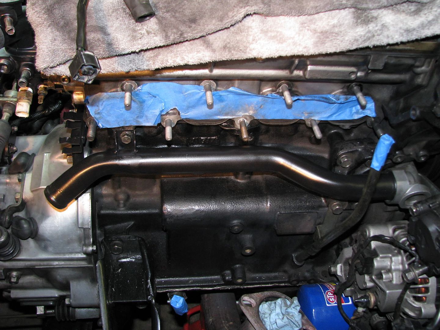
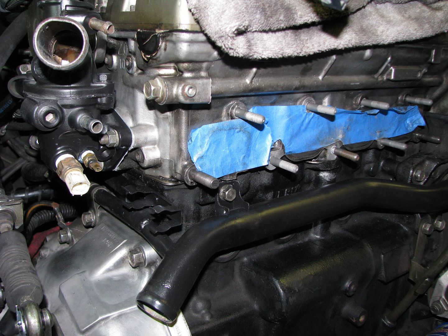
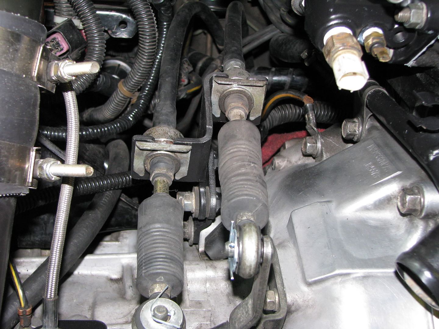
Here it is mocked up to check for the clearance on the water pipe. Look at that shiny compressor housing! =)
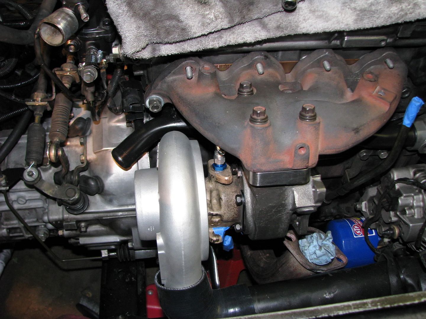
One thing that I forgot to mention is that you should grind down the v-band clamp flange on the outlet of the compressor to get a coupler to fit over it properly. I don't have a closeup pic of that, but you can see from the pic above that I used a 2.5" 90 degree coupler to connect the turbo to my intercooler piping. It met up to the piping just fine, so no modifications needed from the 16g setup!
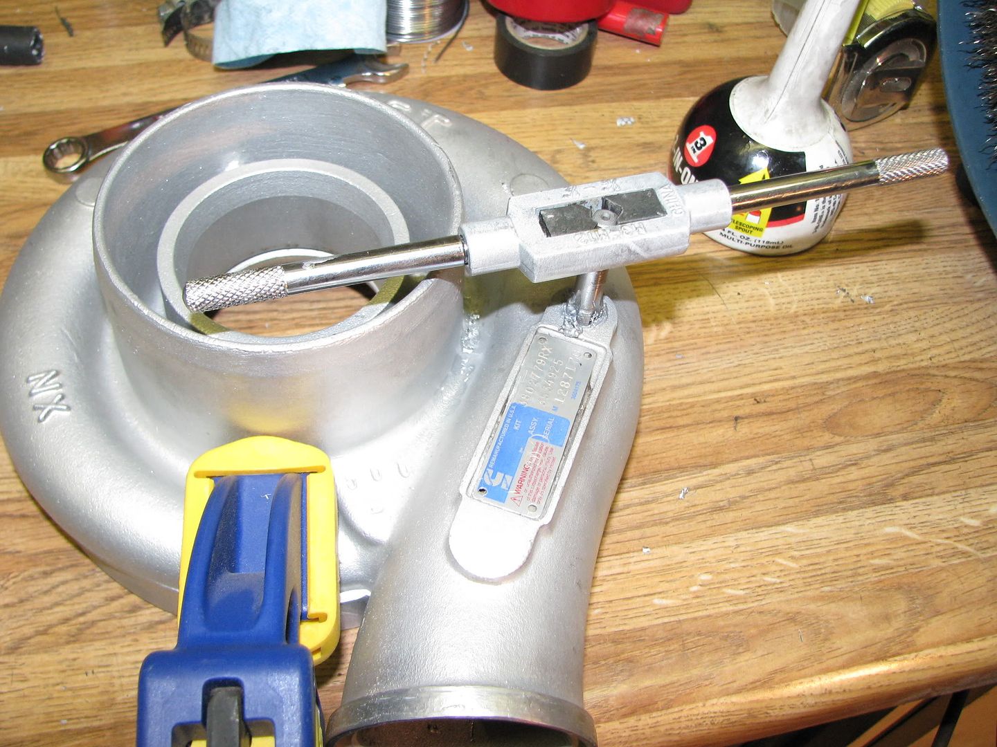
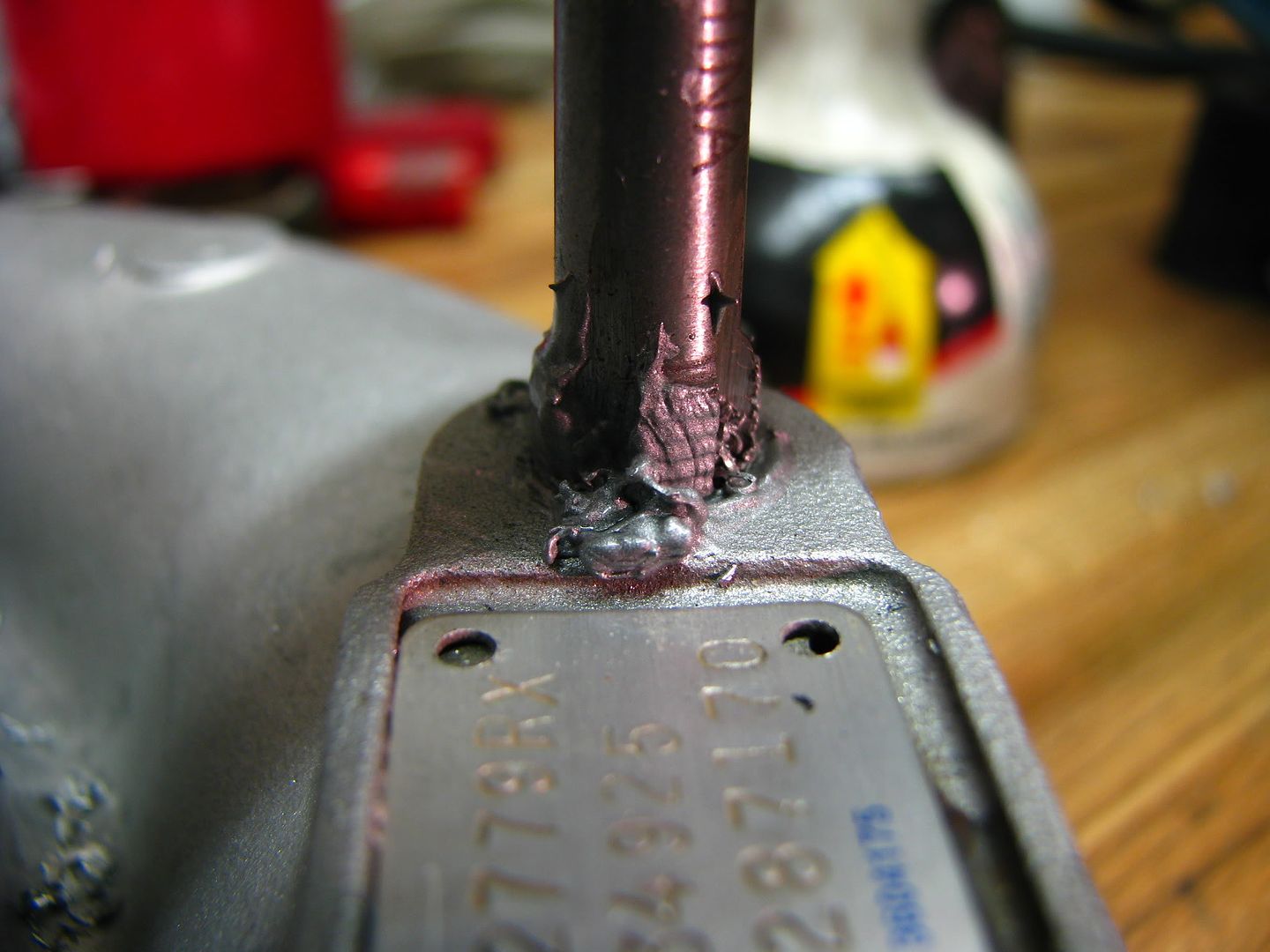
Next thing on my list was to tap into the compressor housing for a boost source to send to the external wastegate. Some Holsets already have a fitting on the compressor housing, but mine didn't, so I drilled and tapped a 1/8NPT hole and put a brass pipe-to-barb adapter from Home Depot on it. Look at the super macro setting on my camer in action!

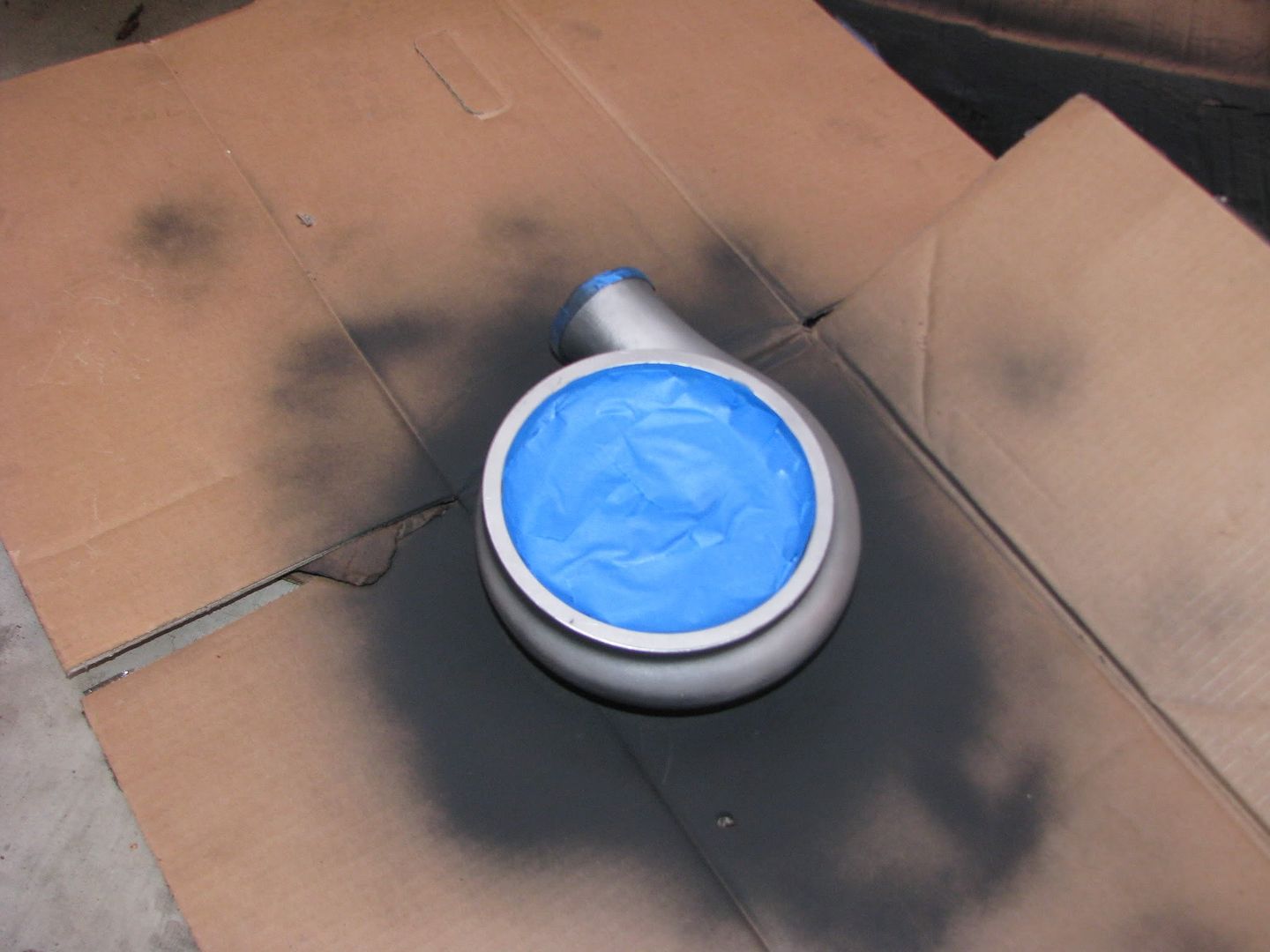
At this point I had to make a decision. In an effort to keep things low key on my car, I usually paint or powder coat things black so they don't stand out and get attention. I was planning on doing that with the compressor housing, but after Dustin cleaned it up it looked so damn nice! After pondering it for quite a while I went ahead and decided to paint it. My only real reservation was not knowing whether painting it would do any good at hiding such a massive turbo.

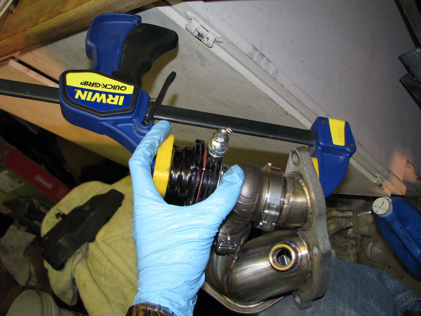
Next I pulled apart my Tial waste gate and put in the proper spring configuration to give me 18lbs of boost. That will be my "low boost" setting. I have an electrical switch hooked up to a manual boost controller which will be set higher, somewhere above 25psi. I actually used a clamp to aid in removing and reinstalling the springs. It's pretty hard to do on your own without some sort of help.
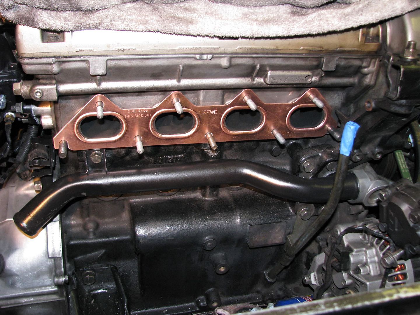
Oh, here's a shot of my shiny copper embossed gasket from FFWD. I also have the FFWD gasket for the exhaust mani to turbo, but I don't have a pic of that. FFWD knows how to make quality parts!
Okay, getting closer! Time to bolt everything up and throw it into the car. Check out the side-by-side comparrison of the old 16g and the new Holset!
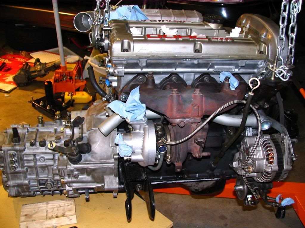
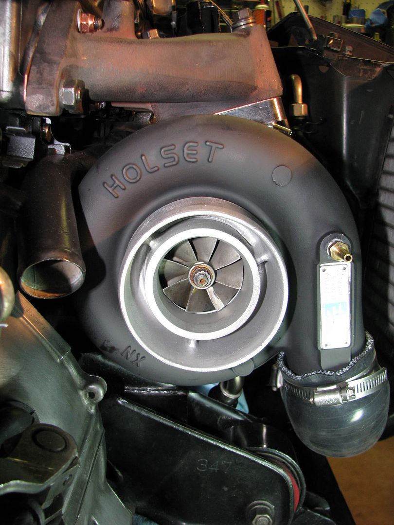
Here's a closer look at the final clearance on the dented water pipe.
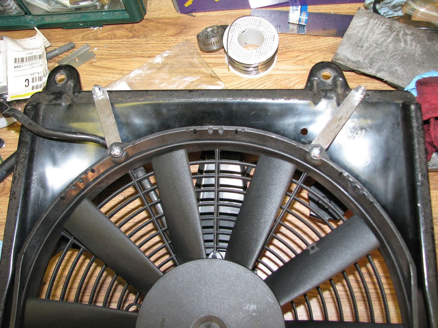
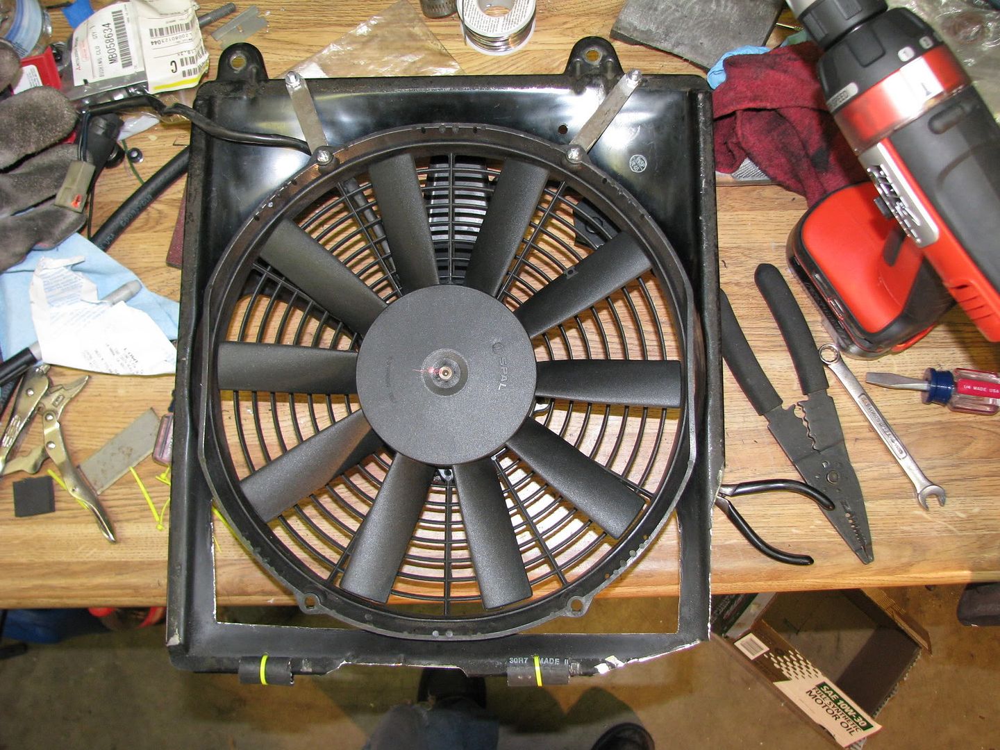
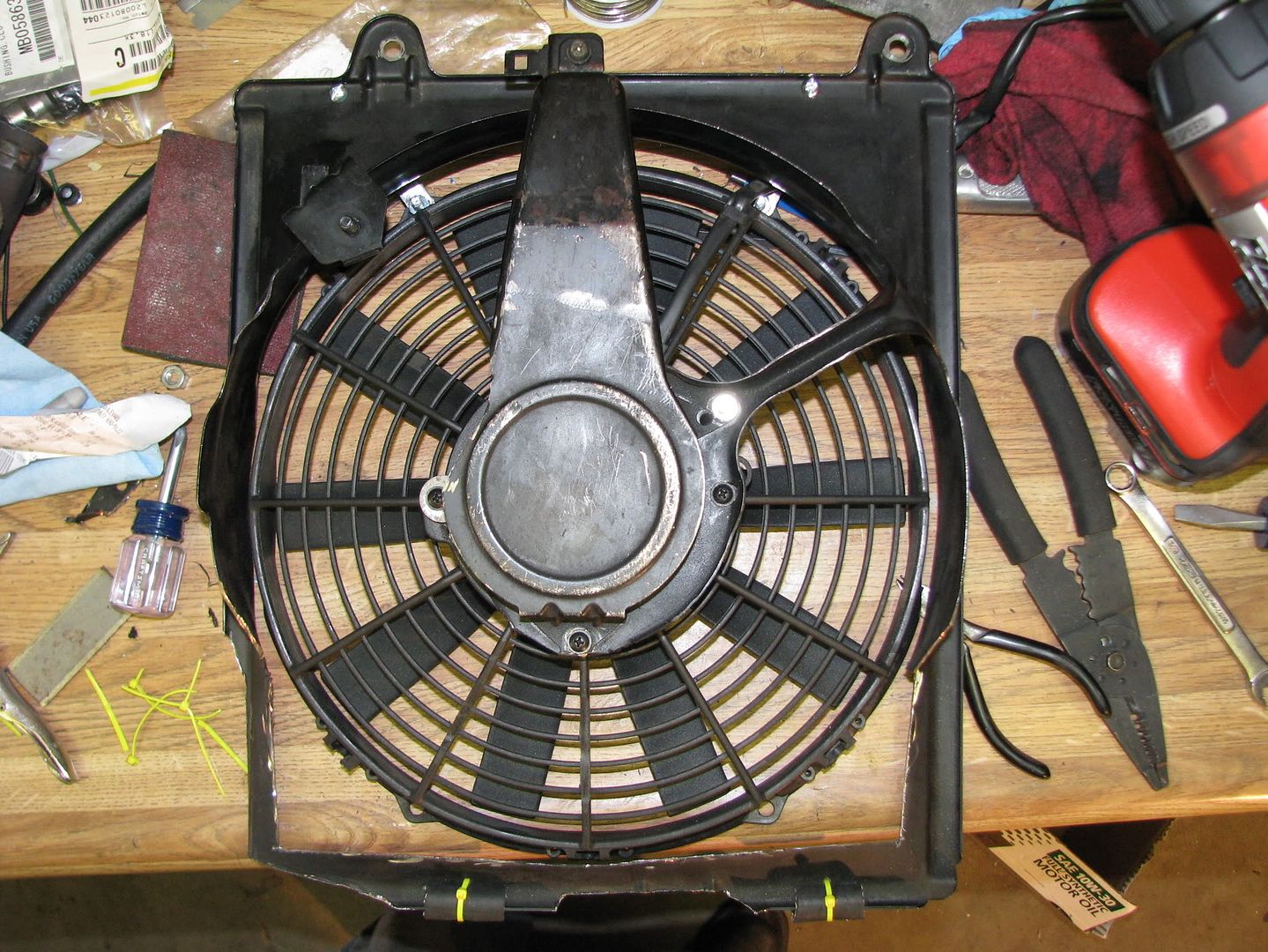
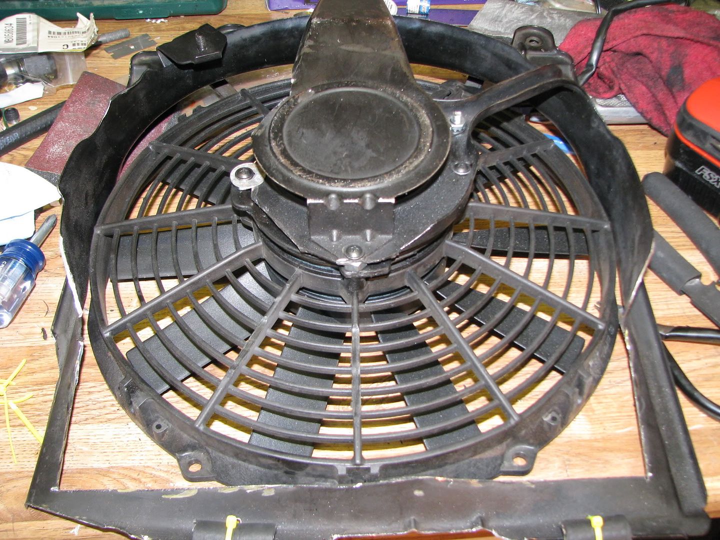
So close, yet so far! In my obsession with keeping the engine bay as stock looking as possible, I decided to modify the fan shrouds to fit in the car with the Holset, which is not simple. There is very little space between the turbo and the radiator. I have aftermarket SPAL fans, and most people throw those on there and toss the stock stuff, but I really wanted to keep the shrouds. I had to chop the bottoms off, and mount the fans to the shrouds. Esier said than done. =P It looks simple, but it actually took me a while to get proper fitment without anything rubbing on one side or the other. This was a few hours worth of work with an angle grinder, a dremmel tool, and some various parts and hardware from Home Depot. I also modified the lower exhaust heat shielding to fit around the waste gate. I didn't document this with pics but you'll see it in the finished product.
Alright, just about done. The next part was hooking up the oil lines. Oiling is a very tricky issue with the Holsets much like the aftermarket Garrett journal bearing turbos that people install. Depending on where you feed the oil from, how adequate your oil return line is, and how much crank case pressure you have, you can end up with too much oil pressure in the turbo which will blow the seals and kill a brand new turbo FAST! (Just ask Wes from LADSM). =P I already had a -4AN oil feed line from the oil filter housing (OFH) for my 16g. The OFH provides clean oil in comparrison to the stock feed location off the head, but it also sends a lot higher oil pressure, especially if you've removed the balance shafts like I did. The answer to this is a restrictor. I bought a simple .075" -4AN billet inline oil restrictor on eBay. I installed it right at the oil filter housing.

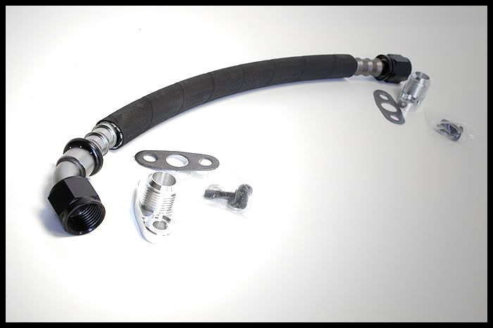
To complete the oil feed line I bought some fittings to mate up to the Holset. The oil return line is also crucial to keeping the oil pressure down. There are several -10AN oil return kits available at various aftermarket shops, but some people argue that -10AN isn't big enough to evacuate the volume of oil that you would be pumping into it. Other people said that -10AN is fine as long as you have a restrictor if you're feeding from the OFH. I ended up buying the -10AN push lock oil return kit from MAPerformance. The only *real* way to be sure your oil pressure is good is to hook up an oil pressure gauge after the restrictor but before the turbo to see exactly how much pressure it is getting. From what I've read, you should see somewhere in the neighborhood of 10psi at idle, and no more than 70psi while revving the motor. I forgot to take pics of the oil return line install, but here's a pick of it from MAPerformance:
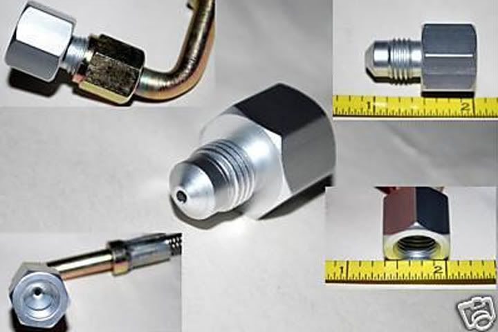
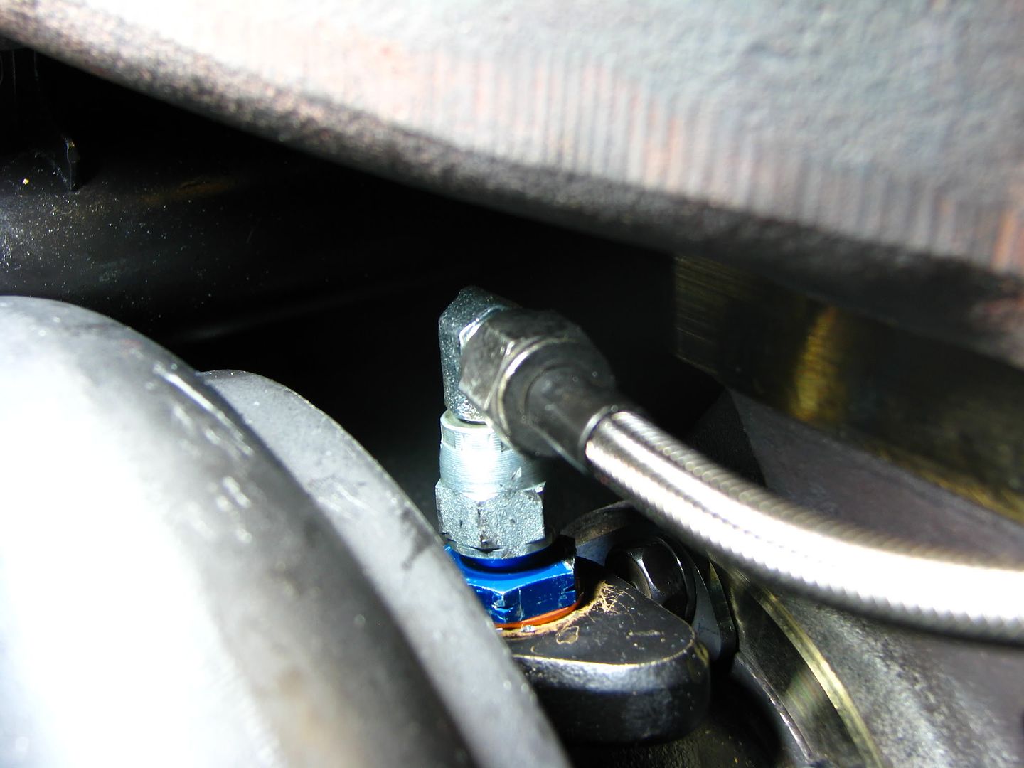
For the oil feed I ended up buying a -4AN to M12x1.5 adapter from Summit Racing to thread into the turbo, as well as a -4AN 90 degree swivel fitting to connect the -4AN line.
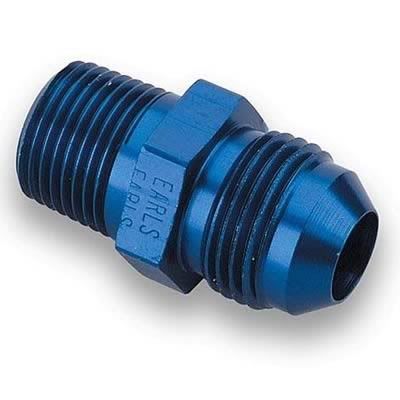

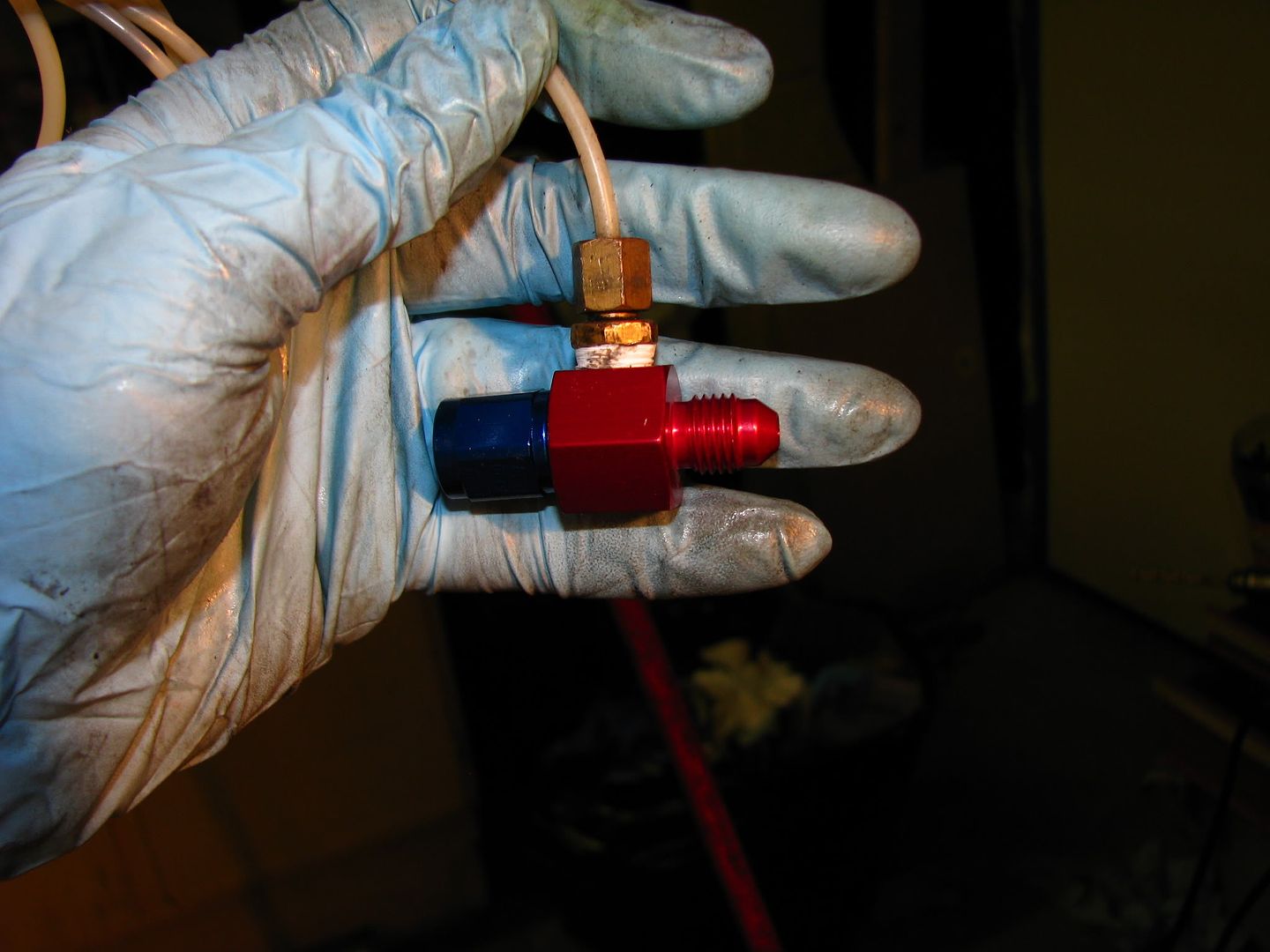
For the oil pressure gauge I bought a -4AN oil pressure adapter fitting. This is an inline swivel fitting that has a 1/8NPT fitting to attach an oil pressure gauge. I put this fitting right at the inlet of the turbo, between the oil feed line and the 90 degree fitting.
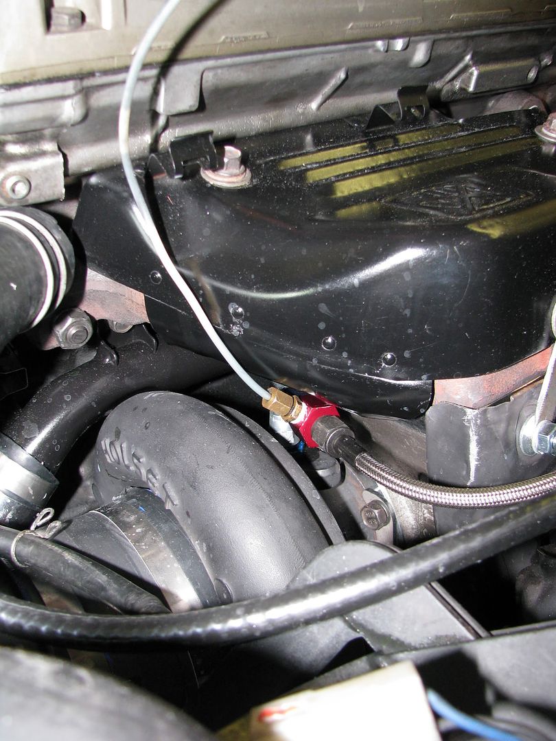
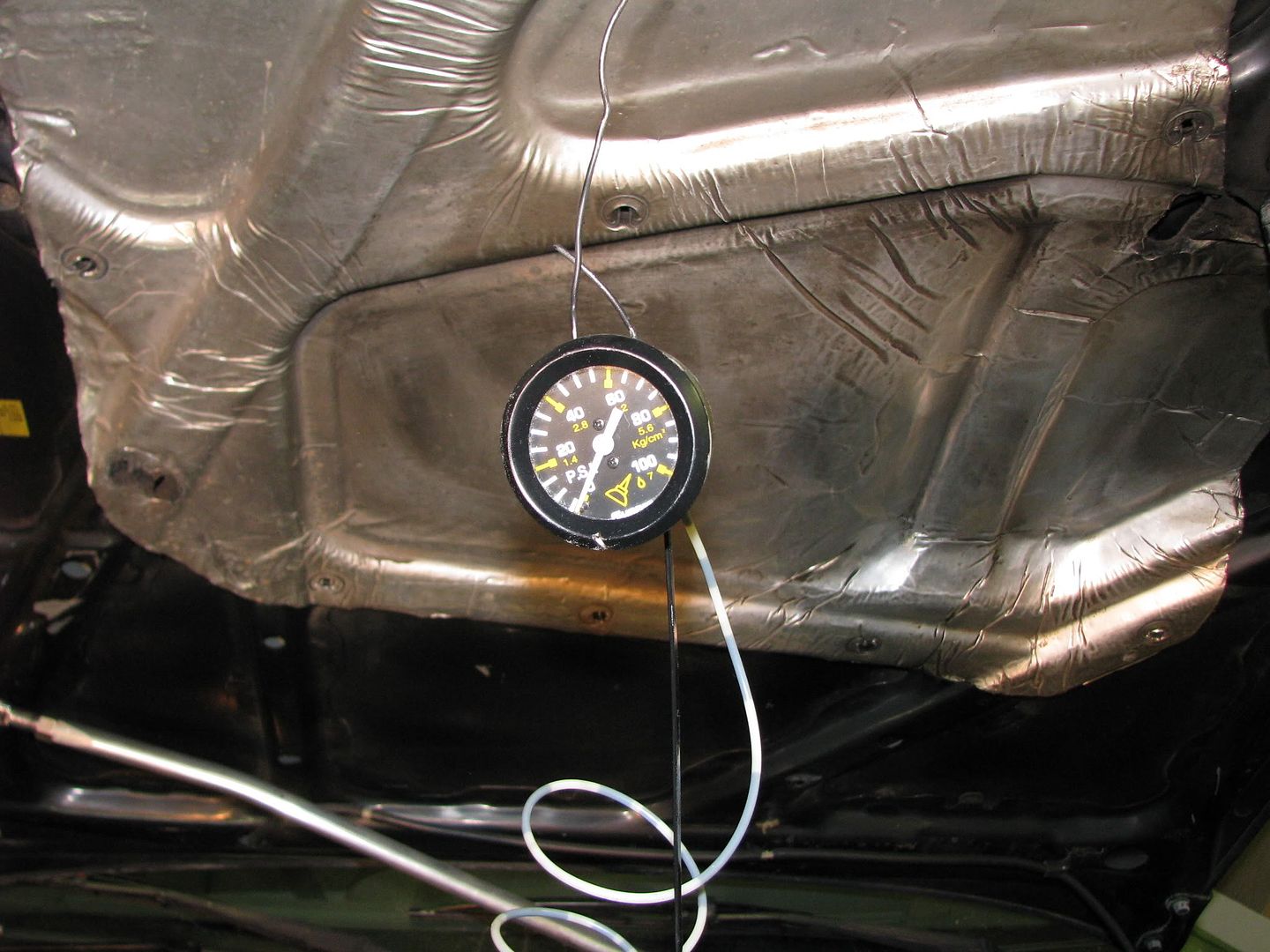
On the home stretch now! All that's left at this point is putting on the intake and installing any other parts that were removed. I purchased the Forced Performance 4" intake pipe used from an LADSM member and put a "Summit Racing" K&N filter on it (you can save a few bucks by ordering the Summit Racing filter, even though it's actually a K&N). This intake pipe doesn't allow room for a MAF on a 1g, so you'll have to have a GM Maf or a speed density setup. I'm using the Jackal software with the Moates Ostrich chip emmulator to run a speed density setup. Once I had everything in place, I checked the oil, added coolant/water, double checked ALL my connections and hardware, and fired it up. It idled perfectly with the base tune from the Jackal software. Oil pressure looked great, so I removed the oil pressure adapter fitting. With some help from one of the guys at DS-Map (home of the Jackal software) I got a basic tune setup and was off and driving! Here's the finished product:
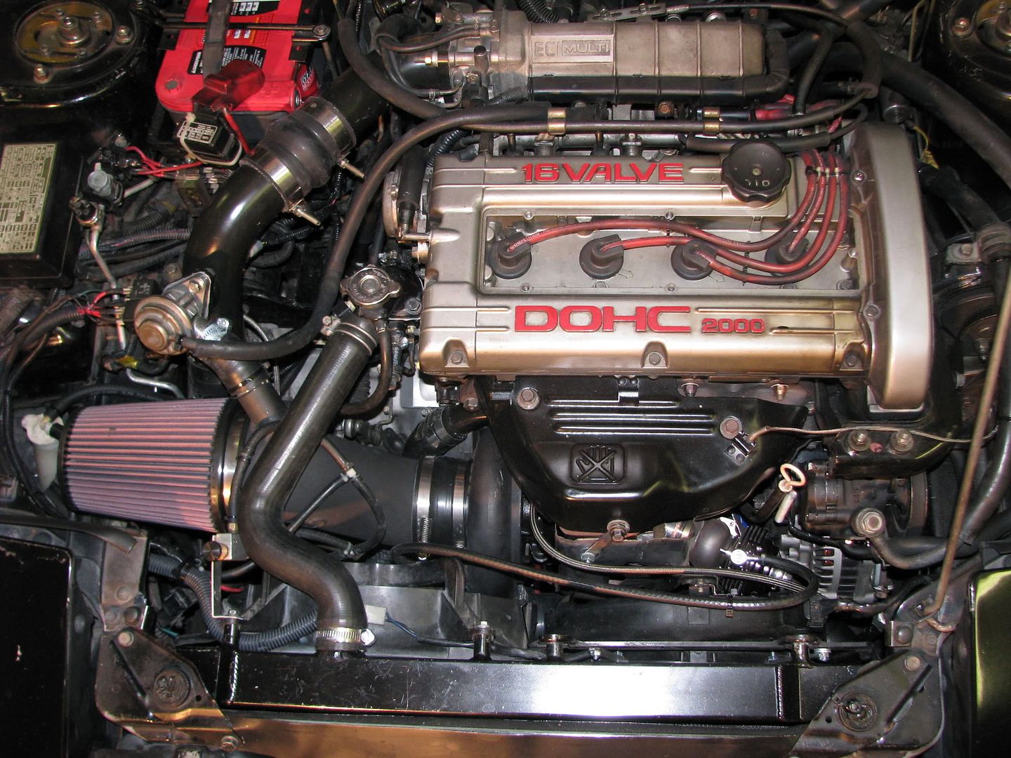
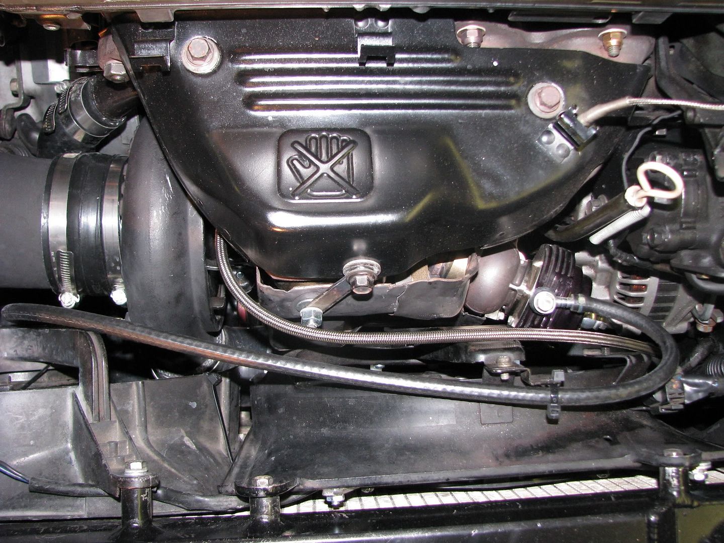
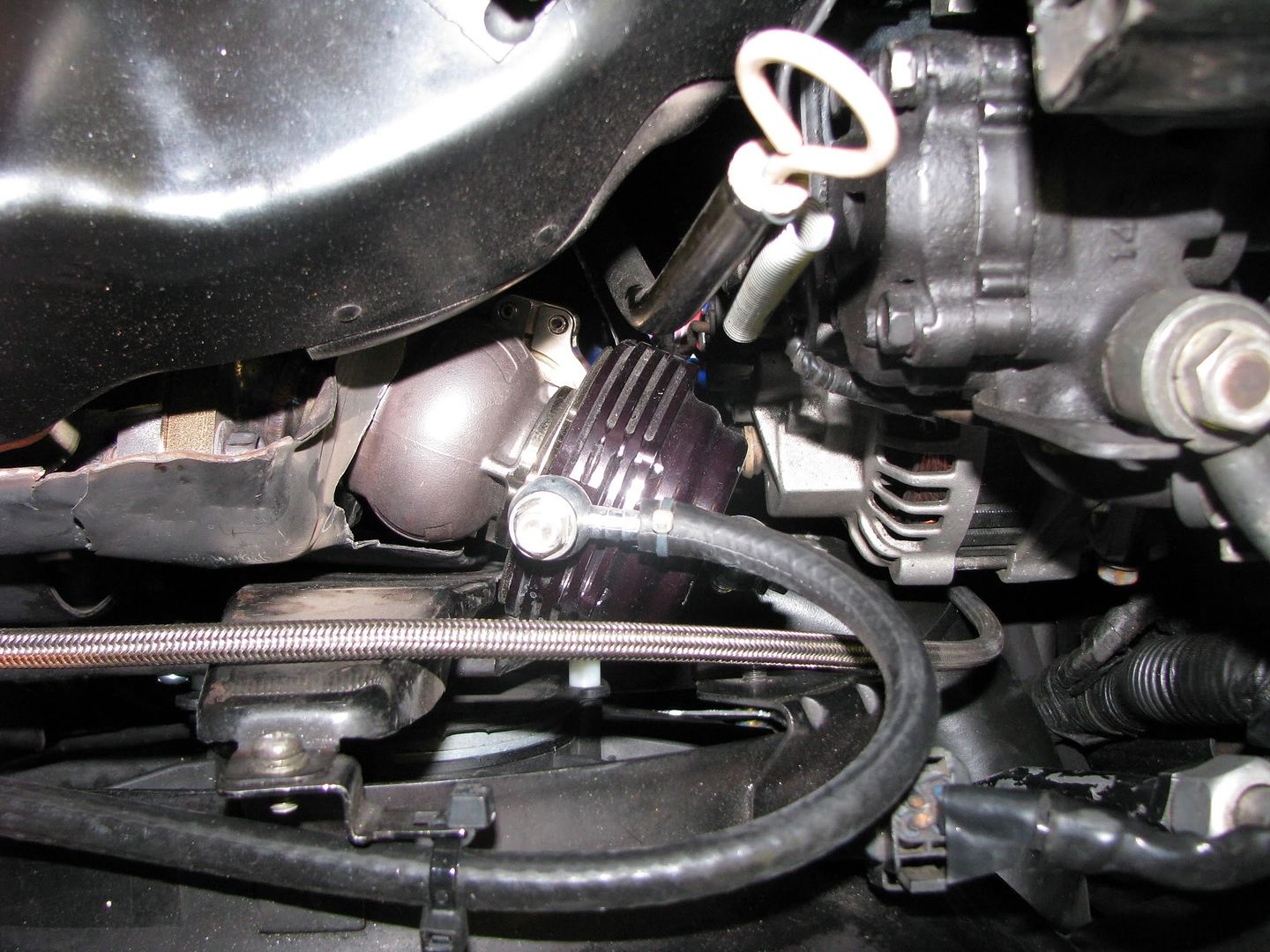
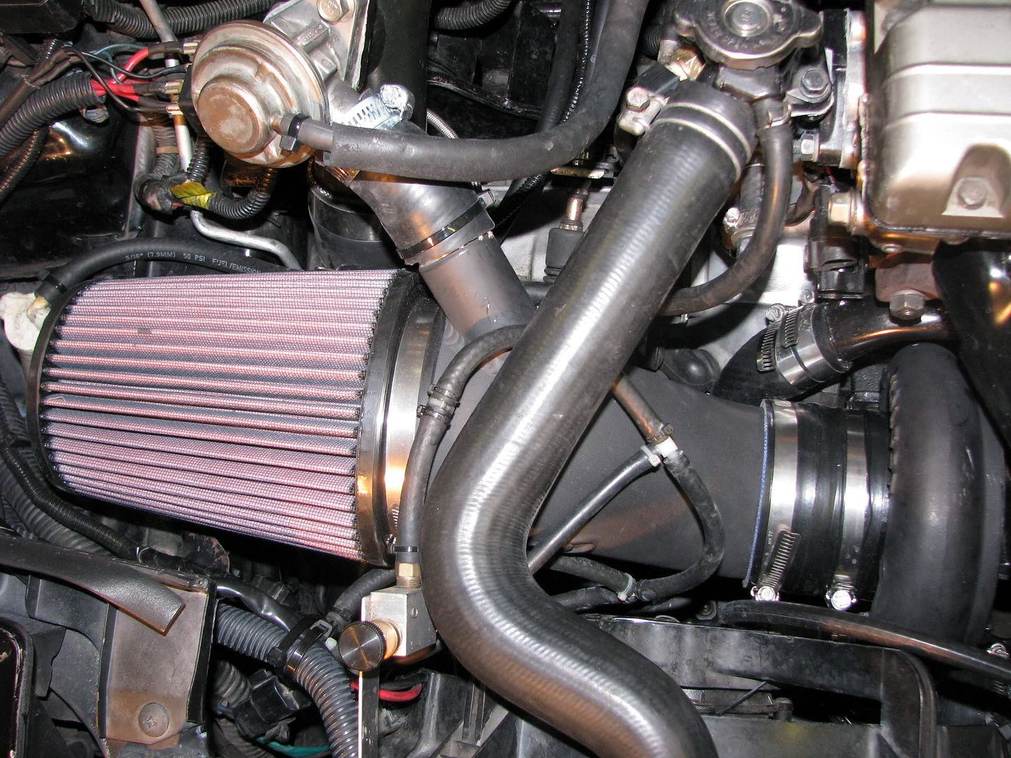
Impressions:
As of this writing, I have only run the turbo up to about 20psi. It already pulls like a monster, but 20psi is barely enough for this turbo to come alive. This turbo has a great sound to it when it spools up. It doesn't help the sleeper effect all that much, but it sounds awesome! =) It spools around 3,600rpm. I was hoping for a few hundred rpm sooner, but I have a significant boost leak that I need to fix. Luckily the boost leak won't affect my tune b/c I'm running a speed density setup, but I can't turn up the boost too much b/c a boost leak will over-work the turbo. Bottom line, I'm extremely happy with the turbo so far, especially for the cost! In the end, considering some of the components were gifts and if you factor in the money I made selling my 16g, the whole setup probably cost me around $200! =) Not bad for how much I got out of it.
As soon as I get finish tuning and get some dyno numbers and/or a timeslip I'll be sure to post it here. Stay tuned!